Transient Analysis of Electrical Circuits Using Runge
advertisement

International Journal of Scientific and Research Publications, Volume 3, Issue 11, November 2013
ISSN 2250-3153
1
Transient Analysis of Electrical Circuits Using RungeKutta Method and its Application
Anuj Suhag
School of Mechanical and Building Sciences, V.I.T University
Abstract- An RLC circuit (or LCR circuit) is an electrical
circuit consisting of a resistor, an inductor, and a capacitor,
connected in series or in parallel. The RLC part of the name is
due to those letters being the usual electrical symbols for
resistance, inductance and capacitance respectively. The circuit
forms a harmonic oscillator for current and will resonate in a
similar way as an LC circuit will.
Index Terms- Damping in, Impedance, Kirchhoff Current
Law, Kirchhoff Voltage Law, Runge Kutta Method, Second
Order Equation
I. INTRODUCTION
T
he time varying currents and voltages resulting from the
sudden application of sources, usually due to switching are
called TRANSIENTS. In transient analysis we start by writing
the circuit equations using basic concepts of KCL, KVL, nodevoltage analysis and mesh-current analysis. Due to the
involvement of integrals and derivatives in current-voltage
relationships for inductances and capacitances, we obtain
integro-differential equations which are converted to pure
differential equations by differentiating with respect to time.
Thus the study of transients requires solving of differential
equations. The order of the differential equation depends on the
number of energy storage elements present in the circuit.
Some Basic Concepts:1. Kirchhoff’s Current Law – The sum of currents flowing in
and out of a node is zero.
For a node,∑ I =0 .
2. Kirchhoff’s Voltage Law –The sum of voltages across various
circuit elements in a mesh is zero.
In a mesh,∑ v =0.
3. Voltage across a capacitor– V = ( ʃ i dt) /C i.e integral of
current flowing through it over a period of time divided by
capacitance
4. Current supplied by capacitor- I = C (dv/dt) i.e product of
capacitance and derivative of voltage across capacitor
with respect to time.
5. Voltage across an inductor- V = L (di/dt) i.e product of
inductance and derivative of current through inductor with
respect to time
6. Current stored in an inductor- I=( ʃ v dt) /L i.e integral of
voltage across it over a period of time divided by inductance.
II. ANALYSIS OF RLC CIRCUIT
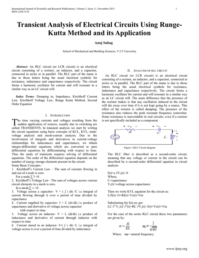
An RLC circuit (or LCR circuit) is an electrical circuit
consisting of a resistor, an inductor, and a capacitor, connected in
series or in parallel. The RLC part of the name is due to those
letters being the usual electrical symbols for resistance,
inductance and capacitance respectively. The circuit forms a
harmonic oscillator for current and will resonate in a similar way
as an LC circuit will. The main difference that the presence of
the resistor makes is that any oscillation induced in the circuit
will die away over time if it is not kept going by a source. This
effect of the resistor is called damping. The presence of the
resistance also reduces the peak resonant frequency somewhat.
Some resistance is unavoidable in real circuits, even if a resistor
is not specifically included as a component.
Figure 1.RLC Circuit diagram
The RLC filter is described as a second-order circuit,
meaning that any voltage or current in the circuit can be
described by a second-order differential equation in circuit
analysis.
I(t)=c.∂Vc(t)/ ∂t
Where,
C=capacitance
Vc(t)=voltage across capacitance
Then we write KVL equation for the circuit as:
L∂I(t)/ ∂t+RI(t)+Vc(t)=Vin
Substituting for I(t),we get:
LC ∂2 Vc (t)/ ∂2(t)+RC ∂Vc(t)/ ∂(t)+Vc(t)=Vin
For the case of the series RLC circuit these two parameters
are given by:
Where
= natural frequency.
www.ijsrp.org
International Journal of Scientific and Research Publications, Volume 3, Issue 11, November 2013
ISSN 2250-3153
A useful parameter is the damping factor, ζ, which is defined
as the ratio of these two,
2
Voltage equation across 2nd Order RLC circuit is given by,
In the case of the series RLC circuit, the damping factor is
given by,
So,
The value of the damping factor determines the type of transient
that the circuit will exhibit.
Some authors do not use ζ and call α the damping factor.
Different conditions for damping factors,
If,
ζ> 1, the system is called over damped.
ζ= 1, the system is called critically damped.
ζ< 1, the system is called under damped.
Now let,
I(t)=x1
Vc(t)=x2
III. FORMULATION OF RK METHOD
Runge–Kutta method is an effective method of solving
ordinary differential equations of 1storder. If the given ordinary
differential equation is of higher order say ‘n’ then it can be
converted to a set of n 1storder differential equations by
substitution.
The Runge-Kutta method uses the formulas:
tk+1=tk+h
Yj+1=Yj+(k1+2k2+2k3+k4)/6 where K=0,1,2….m-1
Where:
k1=hf(tj, Yj)
k2=hf(tj+h/2,Yj+k1/2 )
k3=hf(tj+h/2,Yj+k2/2 )
k4=hf(tj+h,Yj+k3)
Let,
X(i)=x1
Y(i)=x2
Solving the above equation using 4th order R-K method:
f1=h*f(t,x1,x2)
g1=h*g(t,x1,x2)
f2=h*f((t+h/2),(x1+f1/2),(x2+g1/2))
k1 is the increment based on the slope at the beginning of the
interval, using yn;
k2is the increment based on the slope at the midpoint of the
interval, using yn+k1/2 ;
k3is again the increment based on the slope at the midpoint,
but now using yn+k2/2 ;
k4is the increment based on the slope at the end of the
interval, using yn+k3.
g2=h*g((t+h/2),(x1+f1/2),(x2+g1/2))
f3=h*f((t+h/2),(x2+f2/2),(x2+g2/2))
g3=h*g((t+h/2),(x1+f2/2),(x2+g2/2))
f4=h*f((t+h),(x1+f3),(x2+g3)
g4=h*g((t+h),(x1+f3),(x2+g3))
IV. SOLUTION OF THE RLC CIRCUIT
www.ijsrp.org
International Journal of Scientific and Research Publications, Volume 3, Issue 11, November 2013
ISSN 2250-3153
3
x1=x1+((f1+f4)+2*(f2+f3))/6.0
x2=x2+((g1+g4)+2*(g2+g3))/6.0
Where,
h=(Tf-T0 )/n
here:
h=step size
Tf=final time
To=initial time
Example: Let’s take an example to get the transient analysis of
circuit for an over damped system.
Let:
Figure 2. Voltage Vs time graph for over damped conditions
B. Critically Damped Conditions
let us take R=200Ω
R=300, L= 10mH,C=1uF and Vin=10V
Here,
then,
α=10000 and ζ=1.5
I(0)=0,Vc(0)=0
A plot for voltage developed across capacitor and time for a time
interval of 1ms
SO, W0 =1000
This gives a result with magnitude 15000
Now, after dividing the two values we get 1.5, therefore the
condition is over damped
V. GRAPHS FOR DIFFERENT CONDITIONS OF DAMPING
A. Over Damped Condition
Figure 3. Voltage Vs time graph for critically damped
A plot for voltage developed across capacitor and time for a
time interval of 1ms. This graph shows that as the time increases,
the voltage also increases parabolic ally. The voltage reaches
steady state at or after 1 millisecond
The voltage here varies parabolic ally with time but it reaches
steady state much before 1 millisecond.
www.ijsrp.org
International Journal of Scientific and Research Publications, Volume 3, Issue 11, November 2013
ISSN 2250-3153
4
c=0.000001;
C. Under Damped Conditions
l= 0.01; r=300; Vin=10 ;
Let us take R=100Ω
f=@(t,x1,x2) x2/c;
Then,
g= @(t,x1,x2)((Vin-x1-r*x2)/l);
α=5000 and, ζ=0.5
fprintf('time\t\tvoltage\tcurrent\n');
A plot for voltage developed across capacitor and time for a time
interval of 1ms
for t=0:h:T
fprintf('%f\t%f\t%f\n',t,x1,x2);
X(i)=x1;
grid off Y(i)=x2;
f1=h*f(t,x1,x2);
g1=h*g(t,x1,x2);
f2=h*f((t+h/2),(x1+f1/2),(x2+g1/2));
g2=h*g((t+h/2),(x1+f1/2),(x2+g1/2));
f3=h*f((t+h/2),(x2+f2/2),(x2+g2/2));
g3=h*g((t+h/2),(x1+f2/2),(x2+g2/2));
f4=h*f((t+h),(x1+f3),(x2+g3));
Figure 4. Voltage Vs time for under damped conditions
g4=h*g((t+h),(x1+f3),(x2+g3));
x1=x1+((f1+f4)+2*(f2+f3))/6.0;
VI. MATLAB PROGRAMMING
x2=x2+((g1+g4)+2*(g2+g3))/6.0;
i=i+1;
clear all;
clc
t=0;
T=0.001;
h=0.0001;
x1=0;
x2=0;
end
time=[0:h:T];
plot(time,X,'-p');
grid on;
xlabel('time(s)');
ylabel('voltage(m)');
hold on
i=1;
www.ijsrp.org
International Journal of Scientific and Research Publications, Volume 3, Issue 11, November 2013
ISSN 2250-3153
VII. RESULT AND DISCUSSION
5
From the experiment conducted above, we obtained the
following results for transient analysis:
.
Figure 5. MATLAB Generated final result
This shows that the RK method is very efficient in solving
second order differential equations. Thus, we can conclude that
by carrying out the transient analysis of a system, we can find out
the response of the system by changing the conditions from one
steady state value to another. This response helps in designing a
system which meets our requirements, and we can further
optimize the time domain parameters of the system
REFERENCES
[1]
[2]
[3]
Comparing Numerical Methods for Ordinary Differential EquationssT.E.Hull,W.H.Enright and A.E.Sedgwick (08 th September 1971).
Numerical Analysis of ordinary differential equations:Runge-Kutta method
and general linear methods,-J.C.Butcher,University of Auckland
Advanced Engineering Mathematics,Wiley&Sons Publications by Erwin
Kreyszig Part A Ordinary Differential Equations.
.
AUTHORS
Anuj Suhag, B.Tech. Mechanical, VIT University, Email:
anuj.suhag27@gmail.com.
www.ijsrp.org


