Electromechanical Lock
Installation Instruction
Specifications
Power Input
12/24V DC
Voltage Tolerance
±10%
Current Draw
280m A@12 VDC; 140m A@24 VDC
Version Changeable
Fail-safe/secure changeable
Operating
Temperature
-10~45°C
Humidity
0~95% non-condensing
Lock bolt sensor
switch output
SPDT rated 3A@125VAC
Solenoids testing
Tested to 1,000,000 cycles
Backset
30 mm
Weight
380 g
single swing door
double swing door
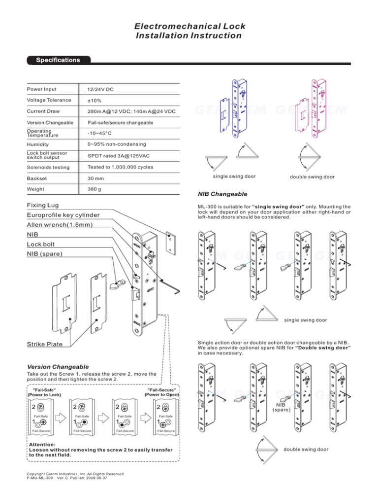
NIB Changeable
Fixing Lug
ML-300 is suitable for “single swing door” only. Mounting the
lock will depend on your door application either right-hand or
left-hand doors should be considered.
Europrofile key cylinder
Allen wrench(1.6mm)
NIB
Lock bolt
NIB (spare)
single swing door
Single action door or double action door changeable by a NIB.
We also provide optional spare NIB for “Double swing door”
in case necessary.
Strike Plate
Version Changeable
Take out the Screw 1, release the screw 2, move the
position and then tighten the screw 2.
"Fail-Secure"
(Power to Open)
"Fail-Safe"
(Power to Lock)
NIB
(spare)
Fail-Safe
Fail-Safe
Fail-Safe
Fail-Safe
Fail-Secure
Fail-Secure
Fail-Secure
Fail-Secure
Attention:
Loosen without removing the screw 2 to easily transfer
to the next field.
Copyright Gianni Industries, Inc. All Rights Reserved.
P-MU-ML-300 Ver. C Publish: 2008.08.07
double swing door
Template
Ø5
Unit: mm
25
Door leaf edge
Door leaf edge
19.5
19.5
Alignment CL
30
Ø 18
Ø 11
86.5
30
Ø5
Alignment CL
CL
30
318
275
150
206
Alignment CL
CL
Cut on dotted line
Alignment CL
Ø5
Ø5
Attention: For “Single swing door” installation, Strike Plate and NIB can be adjusted thru the door opening and closing
direction. (refer to page 1 for related NIB adjustment)
Out-swing
CL
CL
Door frame
Door leaf
Door frame
CL
In-swing
Copyright Gianni Industries, Inc. All Rights Reserved.
P-MU-ML-300 Ver. C Publish: 2008.08.07
Door leaf
CL
Installation Instructions
Do
L
or
ea
f
Door Loop
(Optional)
The Door Loop is for
protection of extension
wiring from damages with
high security concerns.
Fr
am
e
Ø5
(C
28
nd
er
no
30
25
0
12
4
yli
t in
clu
de
d)
15
0
28
30
25
Unit: mm
Ø5
1
Frame
Door Leaf
2
3
Ø5
Do
or
Le
4
af
30
Alignment CL
Ø5
Mortise cutout in door leaf
for face plate .
Locate the vertical centerline
of the magnet and armature as
possible to the leading door
edge.
5
6
Position screws for fasten
Fixing Lugs.
7
Drill and cut as template
indicated.
8
Fr
Connect power cable to
electric dropbolt.
Insert electric dropbolt into
position, attach to Fixing
base and cover.
Copyright Gianni Industries, Inc. All Rights Reserved.
P-MU-ML-300 Ver. C Publish: 2008.08.07
Tighten the cylinder
am
e
Tighten the Strike Plate
Connecting Diagram
Lock bolt sensor switch output
Voltage Selection
For the 12 VDC operation, the electric strikes have to
connect in Parallel .
Black
Red
Black
Control Device
N.C. contact
12 VDC Power supply
Fail-Safe
N. C.
Green
Com.
Blue
N. O.
Yellow
N. O.
Green
Com.
Blue
N. C.
Yellow
N. C.
Green
Com.
Blue
N. O.
Yellow
N. O.
Green
Com.
Blue
N. C.
Fail-Secure
Varistor
"Fail-Safe"
(Power to Lock)
Red
(Power input is polarity free)
Black
Red
Black
Yellow
Control Device
N.O. contact
Fail-Safe
12 VDC Power supply
Varistor
Fail-Secure
Red
"Fail-Secure"
(Power to Open)
(Power input is polarity free)
For the 24 VDC operation, the electric strikes have to
connect in series .
Black
Fail-Safe
Red
Black
Control Device
N.C. contact
24 VDC Power supply
Fail-Secure
Varistor
"Fail-Safe"
(Power to Lock)
Red
(Power input is polarity free)
Black
Red
Black
Control Device
N.O. contact
Fail-Safe
24 VDC Power supply
Varistor
Fail-Secure
Red
(Power input is polarity free)
"Fail-Secure"
(Power to Open)
NOTE: The varistor (or diode) must be connected across the lock terminal (electromagnet...) operated by
the device. The vartistor controls the overload produced by the strike coil (EMP).
Distance in feet from power source to farthest locking device
Minimum
Wire Gauge
for 12 VDC
Minimum
Wire Gauge
for 24 VDC
Copyright Gianni Industries, Inc. All Rights Reserved.
P-MU-ML-300 Ver. C Publish: 2008.08.07


