TW
R A
I RNESLME IS TS T IE/RO
WIO® System
Line of Sight
900 MHz: 6.3 Miles (10.1 Km)
2.4 GHz: 5.7 Mile (9.2 Km)
INPUTS A
INPUTS B
Discrete
4-20 mA
0-10 V
0-10 V
4-20 mA
Discrete
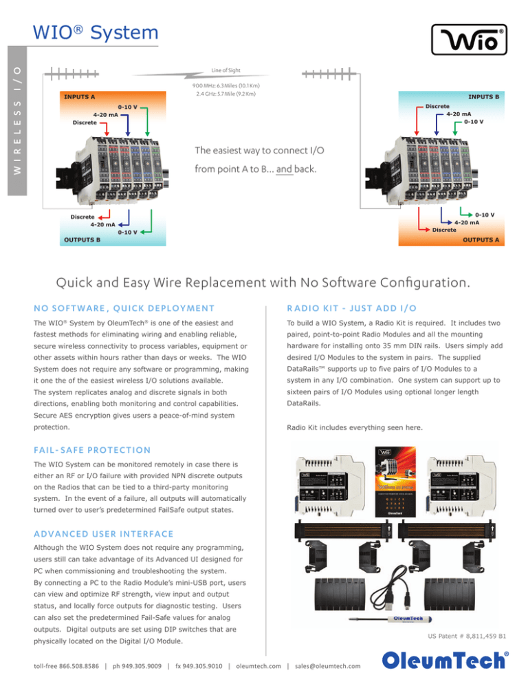
The easiest way to connect I/O
from point A to B... and back.
0-10 V
4-20 mA
Discrete
Discrete
4-20 mA
0-10 V
OUTPUTS B
OUTPUTS A
Quick and Easy Wire Replacement with No Software Configuration.
N O S O F T W A R E , QU IC K DE P LOY M E NT
R ADIO KIT - JUS T ADD I/O
The WIO System by OleumTech is one of the easiest and
To build a WIO System, a Radio Kit is required. It includes two
fastest methods for eliminating wiring and enabling reliable,
paired, point-to-point Radio Modules and all the mounting
secure wireless connectivity to process variables, equipment or
hardware for installing onto 35 mm DIN rails. Users simply add
other assets within hours rather than days or weeks. The WIO
desired I/O Modules to the system in pairs. The supplied
System does not require any software or programming, making
DataRails™ supports up to five pairs of I/O Modules to a
it one the of the easiest wireless I/O solutions available.
system in any I/O combination. One system can support up to
The system replicates analog and discrete signals in both
sixteen pairs of I/O Modules using optional longer length
directions, enabling both monitoring and control capabilities.
DataRails.
®
®
Secure AES encryption gives users a peace-of-mind system
protection.
Radio Kit includes everything seen here.
F AIL- S A F E P R O TE C TION
The WIO System can be monitored remotely in case there is
either an RF or I/O failure with provided NPN discrete outputs
on the Radios that can be tied to a third-party monitoring
system. In the event of a failure, all outputs will automatically
turned over to user’s predetermined FailSafe output states.
A DV AN C E D US ER INTE RFA C E
Although the WIO System does not require any programming,
users still can take advantage of its Advanced UI designed for
PC when commissioning and troubleshooting the system.
By connecting a PC to the Radio Module’s mini-USB port, users
can view and optimize RF strength, view input and output
status, and locally force outputs for diagnostic testing. Users
can also set the predetermined Fail-Safe values for analog
outputs. Digital outputs are set using DIP switches that are
physically located on the Digital I/O Module.
toll-free 866.508.8586 │ ph 949.305.9009 │ fx 949.305.9010 │ oleumtech.com │ sales@oleumtech.com
US Patent # 8,811,459 B1
WIO® System
T E C H N I C A L S P E C I F I C AT I O N S
HARDWARE & SYSTEM
Unique System Features
ANALOG 0-10 V I/O MODULE
Bi-Directional, Paired, Wireless I/O Communication System
Number of Inputs
2 (24-bit Resolution)
No Software or Programming Required
Number of Outputs
2 (16-bit Resolution)
Maximum Network Capacity
Max Capacity Depends on I/O Combination Impacting Power
Signal Range
0 VDC to 10 VDC (10.5 V Max)
When Using More Than 5 Modules
Use Power Budget Calculator http://goo.gl/t67r3k
Isolation Voltage
2500 V r.m.s.
DIN Rail Mounting Compatibility
35 mm x 7.5 mm DIN Rail
Accuracy
< 0.1 % of Full Scale
DataRail™
6.1" / 156 mm - Supports Up to Five (5) I/O Modules
Fail-Safe Output Modes
Last Known Value (Def.) or Any Value on Scale3
(2x Included with Radio Kit)
Other Lengths Also Available
AI Input Impedance
40 K Ohm
I/O Module Slave ID Selection
16-Position Rotary Switch
AO Output Impedance
10 Ohm
DataRail Mounting Hardware
4-Claw Attachment to 35 mm DIN Rail
Power Consumption
Typical: 40 mA / Max: 45 mA @12 VDC
with End Terminal Bracket
Packaging Dimensions
(WxHxD) 4.8 x 5.1 x 2.8-in / 123 x 129 x 72 mm
Built-In Mounting Hardware
Spring-Loaded Clip-On System
Net Dimensions
0.7 x 3.9 x 4.5-in / 17.5 x 99 x 114 mm
Wire Gauge
Solid / Stranded (AWG) 28-12 Gauge
Packaging Weight
Single: 0.5 lbs / 227 g; Double: 0.8 lbs / 363 g
Wire Rating
UL: 300 V RMS, 80 °C and 300 V, 105 °C
Net Weight (Single)
0.3 lbs / 136 g
CSA: 300 V RMS, 105 °C
Warranty
2-Year Limited
RADIO MODULE - 900 MHz or 2.4 GHz
Frequency
902-928 MHz or 2.4 GHz License-Free ISM Band
Antenna Connector Type
SMA (Female Connector)
Default Transmit Speed / Update
1 Second
Turbo Tx Speed Based on
1=100 ms, 2-3=200 ms, 4= 250 ms, 5-6=333 ms,
7-11=500 ms, 12-16=1 second
Number of I/O Modules1
Outdoor / Line of Sight Max Range
2
900 MHz: 6.3 Miles (10.1 Km) / 2.4 GHz: 5.7 Mile (9.2 Km)
Indoor / Urban Range
900 MHz: 1000 ft (305 m) / 2.4 GHz: 300 ft (90 m)
Maximum Transmit Power
900 MHz: 24 dBm (250 mW)
(Adjustable with Advanced UI)
2.4 GHz: 18 dBm (63 mW)
Receiver Sensitivity
900 MHz: -101 dBm / 2.4 GHz: -100 dBm
Spread Spectrum
900 MHz: FHSS / 2.4 GHz DSSS
RF Security
128-bit AES Encryption
Controlled Local Shutdown (ESD)
Yes, via Provided Dry Contact Input
RF Link Alarm Digital Output
Adjustable 2 to 10-Second RF Timeout Trigger (NPN)
ANALOG 4-20 mA I/O MODULE
Number of Inputs
2 (24-bit Resolution)
Number of Outputs
2 (16-bit Resolution)
Signal Range
4 mA to 20 mA
Isolation Voltage
2500 V r.m.s.
Accuracy
< 0.2 % of Full Scale
Internal Loop Power
+13.5 VDC
Maximum Current
84 mA @ 12 VDC
Fail-Safe Output Modes
Last Known Value (Def.) or Any Value on Scale3
AI Input Impedance (loop) 128 Ohm
AO Terminal Voltage Range 10 VDC Min. / 31.5 VDC Max.
Power Consumption
Typical: 50 mA / Max: 75 mA @12 VDC
Packaging Dimensions
(WxHxD) 4.8 x 5.1 x 2.8-in / 123 x 129 x 72 mm
Net Dimensions
0.7 x 3.9 x 4.5-in / 17.5 x 99 x 114 mm
Packaging Weight
Single: 0.5 lbs / 227 g; Double: 0.8 lbs / 363 g
Net Weight (Single)
0.3 lbs / 136 g
DIGITAL I/O MODULE
I/O Link Alarm Digital Output
I/O Mismatch, Bus or Module Failure (NPN)
RF Link Diagnostics (Left LED)
Green = RF Traffic / Yellow = RF Link Fail
Number of Inputs
4
I/O Link Diagnostics (Right LED)
Green = I/O OK, Modules Detected / Red = I/O Link Fail
Number of Outputs
4
Supply Voltage Range
9 - 30 VDC (±5 %)
Input Voltage Range
3-30 VDC
Reverse Polarity Protection
Yes
Isolation Voltage
2500 V r.m.s.
Test RSSI, Tx Power Adjustment, Force Local Output(s),
Input Voltage Threshold
Signal ("H"): > 2.3 VDC
Output Rating
1 A Sink Current for
Fail-Safe Output Modes
On, Off, or Last Known Value (Default)
Advanced User Interface Features
Set Fail-Safe Parameters, and Additional Diagnostics
Power Consumption
35 mA @ 12V AVG (10% Duty Cycle)
Packaging Dimensions (WxHxD)
5.5 x 10.1 x 2.8-in / 140 x 257 x 72 mm
Net Dimensions
0.7 x 3.9 x 4.5-in / 17.5 x 99 x 114 mm
0 Signal ("L"): < 1.1 VDC
Open-Drain Outputs / NPN
Packaging Weight
1.3 lbs / 590 g
Green LEDs
Line-Driven Input Indicators
Net Weight (Single Radio)
0.3 lbs / 136 g
Red LEDs
Output Indicators
Power Consumption
Typical: 18 mA / Max: 26 mA @12 VDC
-40 °C to 80 °C / -40 °F to 176 °F
-20 °C to 80 °C / -4 °F to 176 °F
Humidity
0 to 99 %, Non-condensing
Degree of Protection
IP20 / Plastic
0.7 x 3.9 x 4.5-in / 17.5 x 99 x 114 mm
Packaging Weight
Single: 0.5 lbs / 227 g; Double: 0.8 lbs / 363 g
Net Weight (Single)
0.3 lbs / 136 g
Hazardous Locations Classifications Class I; Division 2 (Zone 2): CSA, ATEX, IECEx
ORDERING INFORMATION
RF Emissions
WIO System Radio Kit
FCC Part 15/IC
¹Response time based on number of I/O Modules.
²The maximum RF range data was collected under optimal test conditions, including a clear line of sight between
antennas. Actual wireless RF range may vary depending on location, RF interference, weather, antenna type,
cable type, and line of sight.
³Requires WIO System Advanced User Interface to set a specific value on Analog I/O Modules.
900 MHz: BM-0900-RM1K
2.4 GHz: BM-2400-RM1K
0-10 V I/O
2-Pack: BM-A010-122D
4-20 mA I/O
2-Pack: BM-A420-122D
Digital I/O
2-Pack: BM-D100-144D
S0 0O
I99001
O
1
RE
toll-free 866.508.8586 │ ph 949.305.9009 │ fx 949.305.9010 │ oleumtech.com │ sales@oleumtech.com
eumTec
Ol
h
Corporation
G
IS
Y
Operational Temperature
Ambient Temperature
(WxHxD) 4.8 x 5.1 x 2.8-in / 123 x 129 x 72 mm
Net Dimensions
TE
N
SAFETY & COMPLIANCE
Packaging Dimensions
R E D CO M
PA
©2015 OleumTech Corporation. All rights reserved. OleumTech and WIO are registered trademarks of OleumTech Corporation in the United States. Specifications, design, and product descriptions
subject to change without notice. This device contains proprietary intellectual property protected by US Patent #6967589. Document ID: 67-4055-001_L
MADE IN USA


