Development of Dye-sensitized Solar Cells
advertisement
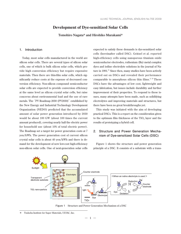
ULVAC TECHNICAL JOURNAL (ENGLISH) No.70E 2009 Development of Dye-sensitized Solar Cells Tomohiro Nagata* and Hirohiko Murakami* expected to satisfy these demands is dye-sensitized solar 1. Introduction cells (hereinafter called DSC). Grätzel et al. reported Today, most solar cells manufactured in the world are high-ef ficiency cells using nanoporous titanium oxide silicon solar cells. There are several types of silicon solar semiconductor electrodes, ruthenium (Ru) metal complex cells, one of which is bulk silicon solar cells, which pro- dyes and iodine electrolyte solutions in the journal of Na- vide high conversion efficiency but require expensive ture in 1991.1) Since then, many studies have been actively materials. Then there are thin-film solar cells, which sig- carried out on DSCs and revealed their per formance nificantly reduce costs at the expense of decreased con- comparable to amorphous silicon thin films. 2, 3) These version efficiency. Non-silicon compound semiconductor DSCs have the advantages of low cost, lightweight and solar cells are expected to provide conversion efficiency easy fabrication, but issues include durability and further at the same level as silicon crystal solar cells, but raise improvement of their properties. To respond to these is- concerns about environmental load and the use of rare sues, many attempts have been made, such as solidifying metals. The“PV Roadmap 2030 (PV2030)”established by electrolytes and improving materials and structures, but the New Energy and Industrial Technology Development there have been no great breakthroughs yet. Organization (NEDO) predicted that the accumulated This study was initiated with the aim of developing amount of solar power generation introduced by 2030 practical DSCs. This is a report on the consideration given would be about 100 GW (about 100 times the current to the optimum film thickness of the TiO2 layer and the amount produced), covering nearly half the electric power results of prototyping a hybrid cell. for household use (about 10% of total electric power). The Roadmap set a target for power generation costs at 7 2. Structure and Power Generation Mechanism of Dye-sensitized Solar Cells (DSC) yen/kWh. The power generation cost of current silicon crystal solar cells is about 40 yen/kWh and there is demand for the development of new low-cost high-efficiency Figure 1 shows the structure and power generation non-silicon solar cells. One of next-generation solar cells principle of a DSC. It consists of a substrate with a trans- Figure 1 Structure and Power Generation Mechanism of a DSC * Tsukuba Institute for Super Materials, ULVAC, Inc. 1 Figure 2 DSC Fabrication Flow parent electrode, a dye adsorption titanium dioxide (TiO2) easily extracted with a current density on the order of nano-particle layer formed over it, an electrolyte, and a mA/cm2. counter electrode substrate. In most cases, an electrolyte solution containing iodine redox couples is used as an 3. Fabrication of DSCs electrolyte due to its performance. The power generation mechanism of a DSC structured in this way is described Figure 2 shows cell fabrication processes. TiO2 nano- below. First, light is irradiated into a dye, exciting elec- par ticle paste (par ticle diameter of about 20 nm) is trons in the dye. The electrons are injected into TiO2 and dropped on a fluorine-doped tin oxide (FTO) glass sub- diffuse, reaching the electrode. On the counter electrode, strate masked with tape, and is spread with a glass rod to − form a particle film. The thickness of the particle film is electrons are injected into the electrolyte and reduce I3 − − ions to I ions (when an iodine electrolyte is used). I ions controlled by the number of applications. The paste ap- diffuse in the solution, reach the dye, give up electrons, plied substrate is calcined at 120℃ for 40 minutes to bond − and are oxidized forming I3 ions. This cycle is repeated particles and is then immersed in a solution of a Ru com- causing power generation by light irradiation. plex dye (N719 dye) in acetonitrile solvent at room tem- The greatest feature of DSCs is the use of a TiO2 nano- perature for 24 hours. After washing it, the glass substrate particle layer, which increases the specific surface area to is attached to the counter electrode using spacers to make about 1000 times the geometric area and thereby increas- space for particles, and the iodine electrolyte is injected es the dye adsorption area. In this way, electricity can be from edges. Table 1 Film Thickness Dependence of Power Generation Properties Number of applications of TiO2 Film thickness (μm) Jsc (mA/cm2) Voc (V) F.F. η( % ) 1 2.1 2.14 0.83 0.62 1.1 2 4.0 4.31 0.83 0.66 2.39 3 6.2 7.70 0.78 0.56 3.36 5 10.2 8.72 0.79 0.68 4.68 7 14.3 8.60 0.77 0.66 4.37 10 20.5 8.19 0.77 0.63 3.97 2 TiO2 film thicknesses within the range of about 10μm to 14μm, and slightly decreases at TiO2 film thicknesses of about 20μm. This behavior can be explained as follows. $VSSFOUEFOTJUZ First, an increase in the TiO2 film thickness increases the dye adsorption area. Therefore, the thicker the film becomes, the more electrons are injected from the dye into TiO2. At the same time, as the film thickness continues to increase, electrons in TiO2 need to move a longer distance to reach the transparent electrode. As a result, recombination occurs and carriers deactivate at a higher 7PMUBHF rate. The results of this verification indicate that there is Figure 3 Film Thickness Dependence of I-V Characteristics less influence of carrier deactivation inside TiO2 and the amount of current increases depending on the amount of dye adsorbed at a film thickness of about 10μm or less. 4. Verification of the Optimum Film Thickness of a TiO2 Electrode Layer In the sample with a film thickness of about 14μm, an increase in the amount of dye adsorbed and an increase in The TiO2 particle layer serves as an under layer for dye the rate of carrier deactivation counteract each other, and adsorption and a transport layer for electrons injected the amount of current ends up at almost the same level as from the dye. It is known that its power generation prop- that of the sample with a film thickness of about 10μm. In erties greatly vary depending on changes in film thick- the sample with a film thickness of about 20μm, the influ- ness, particle diameter and other structural factors. In ence of carrier deactivation becomes larger and reduces this study, we controlled the film thickness by var ying the amount of current compared to the 10μm or 14μm the number of times the nano-particle paste was applied samples that adsorb less dye. and evaluated the power generation properties. Repeated Recent reports have indicated that the optimum film application was done by repeating the cycle of drying the thickness of a TiO2 layer is around 10μm, 4, 5) and, in this applied paste at room temperature, applying more paste study, we obtained results consistent with those reports. and spreading it on again. We used a surface roughness tester for film thickness evaluation, and we used a solar 5. Hybrid Dye/Si-Sensitized Solar Cells simulator (AM1.5, 100 mW/cm2) and a current-voltage (I-V) tester for measuring power generation properties. Ru complex dyes, predominantly used in the DSC field Table 1 shows the TiO2 film thickness dependence of today, have an absorption wavelength range similar to I-V characteristics. Figure 3 is a graph of I-V curves. The that of a-Si, so they can absorb light mainly in the range of current density linearly increased with the TiO2 film thick- 400 to 700 nm which is good for exciting electrons. This ness increase to about 10μm, remains almost the same at Figure 4 Schematic Diagram of a Hybrid Si/Dye Cell Figure 5 I-V Curves of a Conventional Cell and a Hybrid Cell 3 Si allows long-wavelength rays to effectively contribute to power generation. We think specific factors are as follows. As shown in Figure 6, Si has a higher energy level than TiO2 in a conduction band of an electron structure, so that -JHIU TIPSU electrons can be injected into TiO2. On the other hand, the energy of holes in a Si valence band generated by electron excitation is lower than the HOMO level of the -JHIU MPOH Ru complex dye and the redox levels of the iodine electrolyte solution. Therefore, the holes cannot be injected %ZF FMFDUSPMZUF TPMVUJPO into directly. However, it is considered possible to generate a current by recombining these holes with excited electrons of the dye absorbing short-wavelength rays of Figure 6 Power Generation Mechanism of a Hybrid Cell sunlight, injecting the holes into the iodine electrolyte means that this type of DSC ignores all near infrared and solution from the HOMO level of the dye, and flowing the infrared rays at 800 nm or higher contained in sunlight. carriers cyclically. When Si was fixed in the TiO2 layer, To solve this problem, long-wavelength dyes and tandem the number of electrons injected from the dye to TiO 2 dyes with a wide range of power generation wavelengths decreased, but more electrons were excited by absorbing have been actively developed 6–8) , but they have not long-wavelength rays of sunlight that cannot be absorbed reached a practical level yet. by conventional cells, which resulted in the improved current density. The performance of hybrid cells combining a Ru complex dye and a long-wavelength absorbing material are The results of this study indicate the effectiveness of expected to improve over time. However, no satisfactory the hybrid cell that combines a short-wavelength absorb- long-wavelength absorbing dye has been found yet. This ing material and a long-wavelength absorbing material. study adopted silicon (Si), which has a narrow band gap that can absorb long wavelengths, aside from its practica- 6. Conclusion bility, for examination of performance of hybrid cells. Figure 4 shows a schematic diagram of a hybrid dye/Si This study examined the optimum film thickness of a cell, in which Si particles are formed on a TiO2 particle TiO2 layer of DSCs and revealed that about 10μm is the film using an arc plasma gun fabricated by the Advanced optimum thickness. A hybrid cell was prototyped by com- Electronics Equipment Division (refer to Reference 9 for bining Si particles and a Ru complex dye, and it showed details). A TiO2 particle film with a thickness of about improved conversion efficiency at an increased current. 10μm was spread on a FTO glass substrate, and a Si layer Conversion efficiency of around 6% was easily obtained was deposited from a Si target with 40 shots of sparks in this study, due to the simplified fabrication method, using an arc plasma gun. After that, the substrate was im- but conversion efficiency of 10 to 15% will be required for mersed in a Ru complex dye solution at room temperature practical use. We aim to further improve the efficiency by for 24 hours for dye fixation. This substrate was attached introducing long-wavelength absorbing materials other to a counter electrode using spacers to make space for than Si and developing sealing techniques. the particles, and an iodine electrolyte was injected from edges to make a cell. The power generation properties of References the cell were measured with a solar simulator (AM1.5, 100 mW/cm2) and an I-V tester. 1) B. O’ Regan and M. Grätzel : Nature 353 (1991) 737. Figure 5 shows I-V curves of the hybrid cell and a con- 2) Y. Chiba, A. Islam, Y. Watanabe, R. Komiya, N. Koide and L. Han : J. J. Appl. Phys. 45 (2006) L638. ventional cell. Hybridization has resulted in a substantial increase in current density and an improvement of con- 3) M. Grätzel: : Chem. Lett. 34 (2005) 8. version efficiency from 5.3% (for the conventional cell) to 4) M. Murayama, N. Nishikawa, E. Yamazaki, M. Shoya- 6.5%. From this fact, we are lead to believe that the use of ma, N. Hashimoto and K. Matsuyama : Trans. Mater. 4 Res. Soc. Jpn. 29 (2004) 1451. 7) A. Nakasa, H. Usami, S. Sumikura, S. Hasegawa, T. Koyama and E. Suzuki : Chem. Lett. 34 (2005) 501. 5) K. Hara, T. Horiguchi, T. Kinoshita, K. Sayama, H. Sugihara and H. Arakawa : Solar Ener. Mater. Solar 8) Hideki Sugihara : O plus E, Volume 30, No.10 (2008) Cells. 64 (2000) 115. p1021. 9) ULVAC TECHNICAL JOURNAL No.65 (2006) p1. 6) J. He, H. Lindstrom, A. Hagfeldt and S, -E. Lindquist : Solar Ener. Mater. Solar Cells. 62 (2000) 272. 5
