OTPC
transfer switch
open and closed
transition
Features
Description
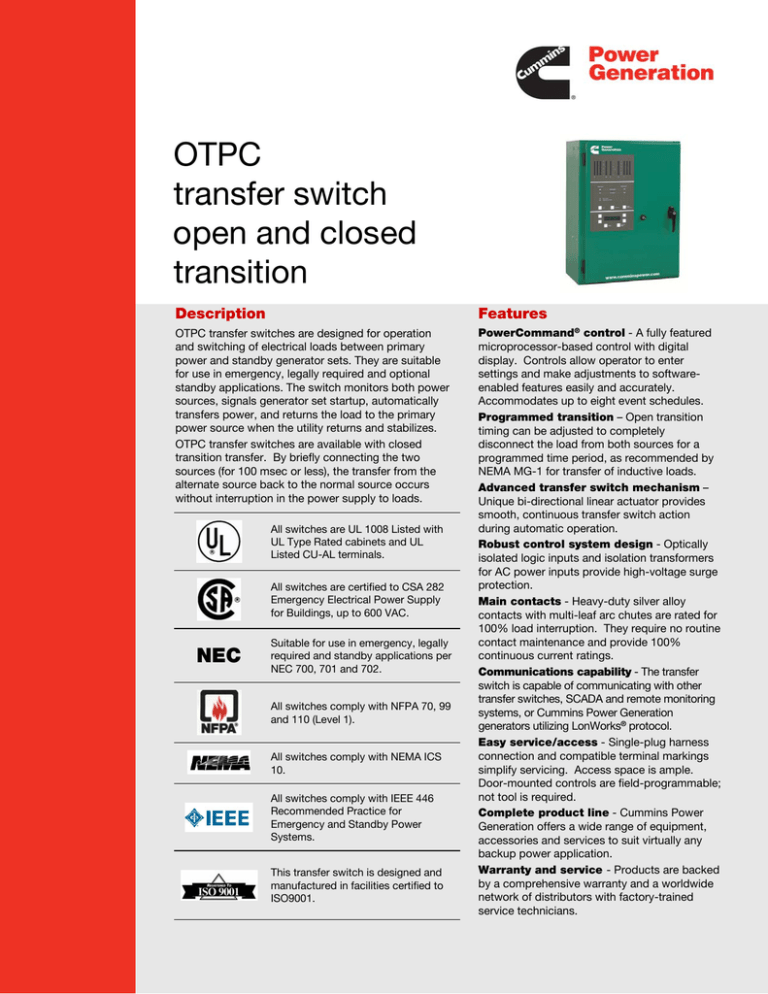
OTPC transfer switches are designed for operation
and switching of electrical loads between primary
power and standby generator sets. They are suitable
for use in emergency, legally required and optional
standby applications. The switch monitors both power
sources, signals generator set startup, automatically
transfers power, and returns the load to the primary
power source when the utility returns and stabilizes.
OTPC transfer switches are available with closed
transition transfer. By briefly connecting the two
sources (for 100 msec or less), the transfer from the
alternate source back to the normal source occurs
without interruption in the power supply to loads.
All switches are UL 1008 Listed with
UL Type Rated cabinets and UL
Listed CU-AL terminals.
All switches are certified to CSA 282
Emergency Electrical Power Supply
for Buildings, up to 600 VAC.
NEC
Suitable for use in emergency, legally
required and standby applications per
NEC 700, 701 and 702.
All switches comply with NFPA 70, 99
and 110 (Level 1).
All switches comply with NEMA ICS
10.
All switches comply with IEEE 446
Recommended Practice for
Emergency and Standby Power
Systems.
This transfer switch is designed and
manufactured in facilities certified to
ISO9001.
PowerCommand® control - A fully featured
microprocessor-based control with digital
display. Controls allow operator to enter
settings and make adjustments to softwareenabled features easily and accurately.
Accommodates up to eight event schedules.
Programmed transition – Open transition
timing can be adjusted to completely
disconnect the load from both sources for a
programmed time period, as recommended by
NEMA MG-1 for transfer of inductive loads.
Advanced transfer switch mechanism –
Unique bi-directional linear actuator provides
smooth, continuous transfer switch action
during automatic operation.
Robust control system design - Optically
isolated logic inputs and isolation transformers
for AC power inputs provide high-voltage surge
protection.
Main contacts - Heavy-duty silver alloy
contacts with multi-leaf arc chutes are rated for
100% load interruption. They require no routine
contact maintenance and provide 100%
continuous current ratings.
Communications capability - The transfer
switch is capable of communicating with other
transfer switches, SCADA and remote monitoring
systems, or Cummins Power Generation
generators utilizing LonWorks® protocol.
Easy service/access - Single-plug harness
connection and compatible terminal markings
simplify servicing. Access space is ample.
Door-mounted controls are field-programmable;
not tool is required.
Complete product line - Cummins Power
Generation offers a wide range of equipment,
accessories and services to suit virtually any
backup power application.
Warranty and service - Products are backed
by a comprehensive warranty and a worldwide
network of distributors with factory-trained
service technicians.
OTPC | 2
Transfer switch mechanism
Transfer switch mechanism is electrically operated and mechanically held in the
Source 1 and Source 2 positions. The transfer switch incorporates electrical and
mechanical interlocks to prevent inadvertent interconnection of the sources.
Independent break-before-make action is used for both 3-pole and 4-pole/
switched neutral switches. This design allows use of sync check operation when
required, or control of the operating speed of the transfer switch for proper transfer
of motor and rectifier-based loads (programmed transition feature).
True 4-pole switching allows for proper ground (earth) fault sensing and consistent,
reliable operation for the life of the transfer switch. The neutral poles of the
transfer switch have the same ratings as the phase poles and are operated by a
common crossbar mechanism, eliminating the possibility of incorrect neutral
operation at any point in the operating cycle, or due to failure of a neutral operator.
High pressure silver alloy contacts resist burning and pitting. Separate arcing
surfaces further protect the main contacts. Contact wear is reduced by multiple
leaf arc chutes that cool and quench the arcs. Barriers separate the phases to
prevent interphase flashover. A transparent protective cover allows visual
inspection while inhibiting inadvertent contact with energized components.
Switch mechanism, including contact assemblies, is third party certified to verify
suitability for applications requiring high endurance switching capability for the life
of the transfer switch. Withstand and closing ratings are validated using the same
set of contacts, further demonstrating the robust nature of the design.
Specifications
Voltage rating
Arc interruption
Neutral bar
Auxiliary contacts
Operating temperature
Storage temperature
Humidity
Altitude
Surge withstand ratings
Total transfer time
(source-to-source)
Manual operation handles
600 VAC, 50 or 60 Hz.
Multiple leaf arc chutes provide dependable arc interruption.
A full current-rated neutral bar with lugs is standard on enclosed 3-pole transfer switches.
Two isolated contacts (one for each source) indicating switch position are provided for customer use.
Contacts are normally open, and close to indicate connection to the source. Wired to terminal block for
easy access. Rated at 10 amps continuous and 250 VAC maximum. UL recognized, and CSA-certified.
-40 F (-40 C) to 140 F (60 C)
-40 F (-40 C) to 140 F (60 C)
Up to 95% relative, non-condensing
Up to 10,000 ft (3,000 m) without derating
Voltage surge performance and testing in compliance with the requirements of IEEE C62.41 (Category B3)
and IEEE C62.45.
Will not exceed 6 cycles at 60 Hz with normal voltage applied to the actuator and without programmed
transition enabled.
Transfer switches rated through 1000 amps are equipped with permanently attached operating handles
and quick-break, quick-make contact mechanisms suitable for manual operation. Transfer switches over
1000 amps are equipped with manual operators. All switches must be de-energized before manual
operation is attempted.
Transition modes
Open transition/programmed: Controls the time required for the device to switch from source to source, so that
the load-generated voltages decay to a safe level before connecting to an energized source. Recommended by
NEMA MG-1 to prevent nuisance-tripping breakers and load damage. Adjustable 0-60 seconds, default 0 seconds.
Programmed transition is standard on 150-1200 amp switches, and optional on 1600-4000 amps.
Open transition/in-phase: Initiates open transition transfer when in-phase monitor senses both sources are in
phase. Operates in a break-before-make sequence. Includes ability to enable programmed transition as a back-up. If
sources are not in phase within 120 seconds, switches from 40-1200 amps will transfer using programmed transition
(not available on open transition switches over 1200 amps).
Closed transition: Used in applications where loads are sensitive to the momentary power interruption that occurs
when performing open transition between sources. Closed transition is accomplished by briefly (<100 msec)
paralleling two good sources to eliminate the momentary break in the power supply.
Closed transition is only available as an option on OTPC models from 1000-4000 amps.
Genset-to-genset: Either genset can be designated as the lead genset. If the lead genset goes down or is taken
offline, the transfer switch starts the second genset and transfers the load. The control can be programmed to
alternate between the two gensets at a set interval up to 336 hours (2 weeks).
S-1270af (1/15)
OTPC | 3
PowerCommand control
PowerCommand controls are microprocessor based and developed specifically for automatic transfer switch operation. The
control includes all of the features and options required for most applications.
LED lamps indicate source availability, source connected, exercise mode and test mode.
Flash memory stores the control settings.
Contents of the memory are not lost even if power to the controller is lost.
On-board battery maintains the real-time clock setting and the engine start time delay.
Choice of two control packages allows selection of the most suitable control for the application.
Control functions
Level 1 control (C023)
Open transition (in-phase)
Open transition (programmed)
Utility-to-genset applications
Software adjustable time delays:
Engine start: 0 to 120 sec
Transfer normal to emergency: 0 to 120 sec
Re-transfer emergency to normal: 0 to 30 min
Engine stop: 0 to 30 min
Programmed transition: 0 to 60 sec
Undervoltage sensing: 3-phase normal, 1-phase
emergency
Accuracy: =/- 2%
Pickup: 85% to 100% of nominal voltage
Dropout: 75% to 98% of pickup setting
Dropout time delay: 0-4 sec
Overvoltage sensing: 3-phase normal, 1-phase emergency
Accuracy: =/- 2%
Pickup: 95% to 99% of dropout setting
Dropout: 105% to 135% of nominal voltage
Dropout time delay: 0 to 120 sec
Over/under frequency sensing:
Accuracy: ±0.05 Hz
Pickup: ±5% to ±20% of nominal frequency
Dropout: 1-5% beyond pickup
Dropout time delay: 0.1 to 15.0 sec
Programmable genset exerciser: One event/schedule
with or w/o load
Basic indicator panel:
Source available/connected LED indicators
Test/exercise/override buttons
Digital display – optional (M018)
Analog bar graph meter display – optional (D009)
Date/time-stamped event recording: 50 events
Load sequencing: Optional with network communications
module M031. Provides control for eight steps of load with an
adjustable time delay for each step on transfer, re-transfer or
both.
Level 2 control (C024)
Open transition (in-phase)
Open transition (programmed)
Closed transition (includes fail-to-disconnect timer to
prevent extended paralleling with the utility)
Utility-to-genset applications
Utility-to-utility applications
Genset-to-genset applications
Software adjustable time delays:
Engine start: 0 to 120 sec
Transfer normal to emergency: 0 to 120 sec
Re-transfer emergency to normal: 0 to 30 min
Engine stop: 0 to 30 min
Programmed transition: 0 to 60 sec
Undervoltage sensing: 3-phase normal, 3-phase emergency
Accuracy: +/- 2%
Pickup: 85% to 100% of nominal voltage
Dropout: 75% to 98% of pickup setting
Dropout time delay: 0-4 sec
Overvoltage sensing: 3-phase normal, 3-phase emergency
Accuracy: ±2%
Pickup: 95% to 99% of dropout setting
Dropout: 105% to 135% of nominal voltage
Dropout time delay: 0 to 120 sec
Over/under frequency sensing:
Accuracy: =/- 0.05 Hz
Pickup: ±5% to ±20% of nominal frequency
Dropout: 1-5% beyond pickup
Dropout time delay: 0.1 to 15.0 sec
Voltage imbalance sensing:
Dropout: 2% to 10%
Pickup: 90% of dropout
Time delay: 2.0 to 20.0 sec
Phase rotation sensing:
Time delay: 100 msec
Loss of single phase detection:
Time delay: 100 msec
Programmable genset exerciser: Eight events/schedules
with or w/o load
Basic indicator panel:
Source available/connected LED indicators
Test/exercise/override buttons
Digital display – standard
Analog bar graph meter display – optional (D009)
Date/time-stamped event recording: 50 events
Load sequencing: Optional with network communications
module M031. Provides control for eight steps of load with an
adjustable time delay for each step on transfer, re-transfer, or
both.
Genset-to-genset: Same functions as above, for lead and
secondary generators.
Utility-to-utility: Same functions as above, for preferred and
alternate source.
S-1270af (1/15)
OTPC | 4
Time-delay functions
Engine start: Prevents nuisance genset starts due to momentary power system variation or loss. Not included in
utility-to-utility systems.
Transfer normal to emergency: Allows genset to stabilize before application of load. Prevents power interruption
if normal source variation or loss is momentary. Allows staggered transfer of loads in multiple transfer switch systems.
For genset-to-genset applications, delays transfer of load from lead to secondary generator.
Re-transfer emergency to normal: Allows the utility to stabilize before re-transfer of load. Prevents needless
power interruption if return of normal source is momentary. Allows staggered transfer of loads in multiple transfer
switch systems. For genset-to-genset applications, delays re-transfer of load from secondary back to lead generator.
Engine stop: Maintains availability of the genset for immediate reconnection if the normal source fails shortly after
retransfer. Allows gradual genset cool down by running unloaded. Not included in utility-to-utility systems.
Elevator pre-transfer signal: Requires optional relay signal module (M023). Signals elevator system that transfer
is pending and delays transfer for pre-set interval of 0-60 seconds to prevent a power interruption during elevator
operation.
User interfaces
Control Options
Basic interface panel
Relay signal module (M023)
LED indicators provide at-a-glance source and transfer
switch status for quick summary of system conditions.
Test and override buttons allow delays to be bypassed
for rapid system checkout.
Provides relay output contacts for sending information to
the building monitoring and control system. Relay
outputs include: Source 1 connected/available, Source 2
connected/available, not in auto, test/exercise active,
failed to disconnect, failed to synchronize, failed to
transfer/re-transfer, and elevator control pre-transfer
signal.
Digital display (M018)
The digital display provides a convenient method for
monitoring load power conditions, adjusting transfer
switch parameters, monitoring PowerCommand
network status or reviewing transfer switch events.
Password protection limits access to adjustments to
authorized personnel. The digital display is optional
with the PowerCommand Level 1 control and comes
standard with the Level 2 control.
User interface options
Front panel security key (M017)
Locks front panel to prohibit access to digital control
settings. Prevents unauthorized activation of transfer or
test functions.
Bar graph meter display (D009)
An LED bar graph display provides an easy-to-read
indicator of the level of power being supplied to the
load. Information displayed includes: 3-phase voltage
and current, frequency, power factor, and kilowatts.
Green, amber, and red LEDs provide at-a-glance
indication of system acceptability. Available as an
option with the Level 2 PowerCommand
microprocessor control.
S-1270af (1/15)
Loadshed (M007)
Removes the load from the emergency power source by
driving the transfer switch to the neutral position when
signaled remotely. Transfers load back to the emergency
source when the signal contacts open. Immediately retransfers back to the primary source when available.
Available for utility-to-genset applications only.
PowerCommand network interface (M031)
Provides connection to the PowerCommand network.
LonWorks compatible for integration with building
monitoring and control system.
Load power and load current monitoring (M022)
Measures load phase and neutral current, power factor,
real power (kW) and apparent power (kVA). Warns of
excessive neutral current resulting from unbalanced or
nonlinear loads. Minimum current level detection is 3%.
OTPC | 5
UL withstand and closing ratings
OTPC transfer switches must be protected by circuit breakers or fuses. Referenced drawings include detailed listings
of specific breakers or fuse types that must be used with the respective transfer switches. Consult with your
distributor/dealer to obtain the necessary drawings. Withstand and closing ratings (WCR) are stated in symmetrical
RMS amperes.
Transfer switch
ampere
40, 70, 125 3-pole
40, 70, 125 4-pole
150, 225, 260
300, 400, 600
800, 1000 open
1000, 1200 closed
1200 open
1600, 2000
3000
4000
MCCB protection
WCR @ volts
max with
specific
manufacturers
MCCBs
14,000 at 480
14,000 at 600
30,000 at 480
30,000 at 600
30,000 at 480
30,000 at 600
65,000 at 480
65,000 at 600
65,000 at 480
50,000 at 600
85,000 at 480
65,000 at 600*
85,000 at 480
65,000 at 600
100,000 at 480
85,000 at 600*
100,000 at 480
85,000 at 600*
100,000 at 480
85,000 at 600*
Special circuit breaker protection
Max MCCB
rating
Drawing
reference
225 A
A050J441
400 A
A048E949
400 A
A048E949
1200 A
A048E951
1400 A
A048E953
1600 A
0098-7312
1600 A
A048E947
4000 A
0098-7311
4000 A
0098-7313
5000 A
0098-8576
With specific
current limiting
breakers (CLB)
200,000 at 480
100,000 at 600
200,000 at 480
100,000 at 600
200,000 at 480
100,000 at 600
200,000 at 480
100,000 at 600
150,000 at 480
100,000 at 600
85,000 at 480
65,000 at 600
200,000 at 480
200,000 at 600
100,000 at 480
85,000 at 600
100,000 at 480
85,000 at 600
100,000 at 480
Max CLB
rating
Drawing reference
225 A
A048J566
400 A
A051D533
400 A
A051D533
1200 A
A048J564
1400 A
A048J562
1600 A
0098-7312
1600 A
A048P186
4000 A
0098-7311
4000 A
0098-7313
5000 A
0098-8576
Fuse protection
Transfer switch
ampere
40, 70, 125
3- and 4-pole
150, 225, 260
300, 400, 600
800, 1000 open
1000, 1200 closed
1200 open
1600, 2000
3000
4000
WCR @ volts
max. with
current limiting
fuses
200,000 at 480
200,000 at 600
200,000 at 480
200,000 at 600
200,000 at 480
200,000 at 600
200,000 at 480
200,000 at 600
200,000 at 480
150,000 at 600*
200,000 at 480
150,000 at 600*
200,000 at 480
150,000 at 600*
200,000 at 480
150,000 at 600*
200,000 at 480
150,000 at 600*
Max fuse, size and type
Drawing reference
200 A Class, J, RK1, RK5, T
A050J441
600 A Class, J, RK1, RK5
1200 A Class L or T
600 A Class, RK1 or RK5
1200 A Class L or T
600 A Class, J, RK1 or RK5
1200 A Class T
2000 A Class L
A048E949
A048E951
A048E953
3000 A Class L
0098-7312
3000 A Class L
A048E947
2500 A Class L
0098-7311
4000 A Class L
0098-7313
6000 A Class L
0098-8576
*CSA only
S-1270af (1/15)
OTPC | 6
3-cycle ratings
Transfer switch
ampere
1000, 1200 closed
1200 open
1600, 2000
3000
4000
WCR @ volts
max 3-cycle
rating
50,000 at 480
42,000 at 600*
50,000 at 480
42,000 at 600*
100,000 at 480
85,000 at 600*
100,000 at 480
85,000 at 600*
100,000 at 480
85,000 at 600*
Max MCCB rating
1600 A
0098-7312
1600 A
A048E947
4000 A
0098-7311
4000 A
0098-7313
5000 A
0098-8576
Transfer switch lug capacities
All lugs accept copper or aluminum wire unless indicated otherwise.
Amp rating
40, 70, 125 3-pole
40 4-pole
70, 125 4-pole
150, 225
260
300, 400
600
800, 1000 open
1000, 1200 closed
1200 open
1600, 2000
3000
4000
Cables per
phase
1
1
1
1
1
1
1 or 2
2
4
4
4
8
8
12
Size
#12 AWG-2/0
#14 AWG-2/0
#6 AWG - 300 MCM
#6 AWG - 300 MCM
#6 AWG - 400 MCM
3/0 - 600 MCM
3/0 - 250 MCM
250 - 500 MCM
250 - 500 MCM
#2 AWG to 600 MCM
0 AWG-750 MCM (Compression lug adaptor Optional)
#2 AWG to 600 MCM (lugs optional)
#2 AWG to 600 MCM (lugs optional)
1/0 AWG to 750 MCM (lugs optional)
Notes
1.
2.
Contact factory for a list of specific lug or compression lugs
Select Feature N032-7
S-1270af (1/15)
Drawing reference
OTPC | 7
Enclosures
The transfer switch and control are mounted in a key-locking enclosure. Switches from 40-1000 amps are wallmounted. Switches from 1200-4000 amps are floor-mounted. Wire bend space complies with 2009 NEC.
Dimensions - transfer switch in UL type 1 enclosure
Depth
Door closed
Amp rating
Height
Width
in
mm
in
mm
in
mm
40, 70, 125 3-pole
27.0
686
20.5
521
12.0
305
40, 70, 125 4-pole
35.5
902
26.0
660
16.0
406
150, 225
35.5
902
26.0
660
16.0
406
260
43.5
1105
28.5
724
16.0
406
300, 400, 600
54.0
1372
25.5
648
18.0
457
800, 1000 open
68.0
1727
30.0
762
20.6
524
1000, 1200 closed
76.3
1937
36.0
915
22.7
577
1200 open
90.0
2290
39.0
991
27.5
699
1600, 2000*
90.0
2290
36.0.
915
48.0
1219
3000*
90.0
2290
36.0
915
48.0
1219
4000*
90.0
2290
46.5
1180
60.0
1520
Door open
in
mm
31.5
800
41.0
1042
41.0
1042
43.0
1093
42.0
1067
48.5
1232
54.0
1372
64.7
1644
84.0
2134
84.0
2134
106
2700
Weight
lb
82
165
165
170
225
360
450
730
1100
1250
1850
Dimensions - transfer switch in UL type 3R, 4 or 12 enclosure
Depth
Amp rating
Height
Width
Door closed
in
mm
in
mm
in
mm
Door open
in
mm
Weight
lb
kg
Outline drawing
kg
37
75
75
77
102
163
204
331
499
567
839
40, 70, 125 3-pole
34.0
864
26.5
673
12.5
318
36.5
927
125
57
40, 70, 125 4-pole
42.5
1080
30.5
775
16.0
406
44.0
1118
190
86
150, 225
42.5
1080
30.5
775
16.0
406
44.0
1118
215
97
260
46.0
1168
32.0
813
16.0
406
46.0
1168
255
102
300, 400, 600
59.0
1499
27.5
699
18.5
419
41.5
1054
290
132
800, 1000 open
73.5
1867
32.5
826
20.8
529
49.5
1257
410
186
1000, 1200 closed
76.3
1937
36.0
915
22.7
577
54.0
1372
450
204
1200 open
90.0
2290
39.0
991
27.5
699
64.7
1644
730
331
1600, 2000*
3000*
4000*
90.0
90.0
90.0
2290
2290
2290
38.0
38.0
49.0
826
965
1244
50.9
51.0
60.0
1293
1295
1524
80.0
84.5
105
2032
2146
2654
1100
1250
1850
499
567
839
Dimensions - transfer switch in UL type 4X stainless steel enclosure
Depth
Door closed
Door open
Amp rating
Height
Width
in
mm
in
mm
in
mm
in
mm
40, 70, 125 3-pole
46.0
1168
32.0
813
16.0
406
46.0
1168
40, 70, 125 4-pole
46.0
1168
32.0
813
16.0
406
46.0
1168
150, 225
46.0
1168
32.0
813
16.0
406
46.0
1168
260
46.0
1168
32.0
813
16.0
406
46.0
1168
300, 400, 600
73.5
1867
32.5
826
19.5
495
49.5
1257
800, 1000 open
73.5
1867
32.5
826
19.5
495
49.5
1257
1000, 1200 closed
70.0
1778
40.0
1016
19.8
502
59.0
1499
1200 open
90.0
2290
39.0
991
27.5
699
64.7
1644
1600, 2000
90.0
2290
35.5
826
50.9
1293
80.0
2032
Weight
lb
255
255
255
255
410
410
450
730
1100
kg
102
102
102
102
186
186
204
331
499
0310-0544
0500-4896
0310-0414
0310-0540
0310-1307
0310-0417
0310-0482
A030L605
0310-0483
0310-0484
0500-4485
Cabinet
type
Outline
drawing
3R, 12
4
3R, 12
4
3R, 12
4
3R, 12
4
3R, 12
4
3R, 12
4
3R, 12, 4
3R, 12
4
3R, 12, 4
3R
3R
0310-0453
0310-0445
0500-4896
0500-4896
0310-0454
0310-0446
0310-0455
0310-0447
0310-1315
0310-1316
0310-0457
0310-0449
0310-0482
A030L605
A041N372
0310-0744
0310-0745
0500-4486
Cabinet
type
Outline
drawing
4X
4X
4X
4X
4X
4X
4X
4X
4X
0500-4184
0500-4896
0500-4184
0500-4184
0500-4185
0500-4185
0310-0482
A041N372
0310-0744
* Rear and side access is required for installation. Dimensions shown are for 4-pole. For information on 3-pole switches, call factory.
S-1270af (1/15)
OTPC | 8
Submittal detail
Amperage ratings
40
70
125
150
225
260
300
400
600
800
1000
1200
1600
2000
3000
4000
Voltage ratings
R020 120*
R038 190
R021 208
R022 220
R023 240
R024 380
R025 416
R035 440
R026 480
R027 600
* Single phase connection (not available on 1200-4000 amps)
Pole configuration
A028 Poles - 3 (solid neutral)
A029 Poles - 4 (switched neutral)
Frequency
A044 60 Hertz
A045 50 Hertz
Transfer mode
A077 Open transition/in-phase
A078 Open transition/programmed
A079 Closed transition (available 1000-4000 amps, for closed
transition below 1000 amps, see CHPC spec sheet S1437)
Application
A035 Utility to genset
A036 Utility to utility
A037 Genset to genset
System options
A041 Single Phase, 2-wire or 3-wire (not available 1200-4000
amps)
A042 Three Phase, 3-wire or 4-wire
Enclosure
B001 Type 1: Indoor use, provides some protection against
dirt (similar to IEC type IP30)
B002 Type 3R:Intended for outdoor use, provides some
protection from dirt, rain and snow (similar to IEC type
IP34)
B003 Type 4: Indoor or outdoor use, provides some
protection from wind-blown dust and water spray
(similar to IEC type IP65)
B004 Open Construction: No enclosure - includes automatic
transfer switch and controls (call factory for
dimensions)
B010 Type 12: Indoor use, some protection from dust (similar
to IEC type IP61)
B025 Type 4X: Stainless steel, indoor or outdoor use,
provides some protection from corrosion (similar to IEC
Type IP65)
S-1270af (1/15)
Standards
A046 UL 1008/CSA certification
A064 NFPA 20 compliant (not available on 1200-4000 amp
switches)
A080 Seismic certification
Controls
C023 PowerCommand control - Level 1
C024 PowerCommand control - Level 2
Control options
M017 Security key - front panel
M018 Digital display
M022 Load monitoring (min current level 3%)
M023 Relay signal module. Includes pre-transfer module for
elevator control
M031 LonWorks network communications module (FTT-10)
Meter
D009 Analog bar graph meter
Battery chargers
K001 2 amps, 12/24 volts
KB59 15 amps, 12 volts
KB60 12 amps, 24 volts
Protective relays (closed transition)
M045 Paralleling timer and lock-out relays, ANSI/IEEE 62PL and
86
M046 Paralleling timer, lock-out and reverse power relays, single
phase, ANSI/IEEE 62PL, 86 and 32R
M047 Paralleling timer, lock-out and reverse power relays, three
phase, ANSI/IEEE 62PL, 86 and 32R
Auxiliary relays - Relays are UL listed and factory installed. All
relays provide two normally closed isolated and two normally open
contacts rated 10 amps at 600 VAC. Relay terminals accept from one
18 gauge to two 12 gauge wires per terminal.
L101 24 VDC coil - installed, not wired (for customer use).
L102 24 VDC coil - emergency position - relay energized when
switch is in Source 2 (emergency) position.
L103 24 VDC coil - normal position - relay energized when switch
is in Source 1 (normal) position
L201 12 VDC coil - installed, not wired
L202 12 VDC coil - emergency position - relay energized when
switch is in Source 2 (emergency) position
L203 12 VDC coil - normal position - relay energized when switch
is in Source 1 (normal) position
Miscellaneous options
M003 Terminal block - 30 points (not wired)
N020 Terminal block – re-transfer inhibit
M007 Load shed - from emergency - drives switch to neutral
position when remote signal contact closes
N009 Power connect - bus stabs (150-1200 amp open
construction only)
N013 Extension harness (open construction only)
Lug kits (select one)
N008 Cable lugs, mechanical, 600 MCM, 8 per pole
N032 Lug adapters, compression, ½ stab (1200A only)
N045 Cable lugs, mechanical, 600 MCM, 4 per pole (1200A only)
N066 Cable lugs, mechanical, 750 MCM, 4 per pole (1200A only)
Warranty
G010 Years 0-2: Parts, labor and travel
Years 3-5: Parts only
Years 6-10: Main contacts only
G013 Years 0-5: Comprehensive
Years 6-10: Main contacts only
Shipping
A051 Packing - export box
Accessories
AC-167 Accessories specifications sheet
OTPC | 9
www.cumminspower.com
North America
1400 73rd Avenue N.E.
Minneapolis, MN 55432 USA
Phone 763 574 5000
Fax 763 574 5298
Asia Pacific
10 Toh Guan Road #07-01
TT International Tradepark
Singapore 608838
Phone 65 6417 2388
Fax 65 6417 2399
Brazil
Rua Jati, 310
Guarulhos – Sao Paulo
CEP – 07180-140
Phone 55 11 2186 4195
Fax 55 11 2186 4729
Europe, CIS, Middle East & Africa
Manston Park Columbus Ave.
Manston Ramsgate
Kent CT 12 5BF United Kingdom
Phone 44 1843 255000
Fax 44 1843 255902
Specifications are subject to change without
notice.
©2015 Cummins Power Generation. All rights
reserved. Cummins Power Generation and
Cummins are registered trademarks of Cummins
Inc. PowerCommand, InPower and “Our energy
working for you.” are trademarks of Cummins
Power Generation.
S-1270af (1/15)


