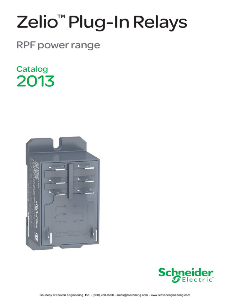
Zelio Plug-In Relays
™
RPF power range
Catalog
2013
Courtesy of Steven Engineering, Inc. - (800) 258-9200 - sales@steveneng.com - www.stevenengineering.com
Courtesy of Steven Engineering, Inc. - (800) 258-9200 - sales@steveneng.com - www.stevenengineering.com
Zelio™ Plug-In Relays
Introduction,
specifications
RPF power relays
Introduction of the product range
5
2
1
2
3
4
5
30 A relays with 2 C/O or 2 N/O contacts
Four or six quick-connect contact terminals
Two relay coil terminals
A locating slot for DIN rail mounting
Two slots for optional panel mounting
1
4
3
General specifications
Conformity to standards
IEC/EN 61810-1, UL 508, CSA C22-2 n°14
Product certifications and standards
UL listed, CSA, CE, GOST, RoHS
Ambient air temperature
around the device
Storage
°C (°F)
- 40 to + 85 (-40 to +185)
Operation
°C (°F)
- 40 to + 55 (-40 to + 131)
Vibration resistance
In operation
conforming to EC/EN 60068-2-6
Not in operation
3 gn (+/- 1 mm, 10 to 150 Hz) 5 cycles
Degree of protection
Conforming to IEC/EN 60529
IP 40
Shock resistance
conforming to
IEC/EN 60068-2-27
In operation
10 gn
Not in operation
30 gn
10 gn (+/- 1 mm, 10 to 150 Hz) 5 cycles
Protection category
RT II
Polution degree
3
Mounting position
Any
Insulation specifications
Rated insulation voltage (Ui)
Rated impulse withstand
voltage (Uimp)
Dielectric strength
(rms voltage)
V
V
kV
4 (1.2 ms / 50 ms)
Between coil and contact
Vac
4000 (reinforced insulation)
Between poles
Vac
2000 (basic insulation)
Between contacts
Vac
1500 (micro-disconnection)
250 (conforming to IEC)
300 (conforming to UL)
3
Courtesy of Steven Engineering, Inc. - (800) 258-9200 - sales@steveneng.com - www.stevenengineering.com
Zelio™ Plug-In Relays
Specifications (continued)
Contact specifications
Relay type
RPF power relays
RPF 2App
Number and type of contacts
Contact materials
Conventional thermal
For ambient
current (Ith)
temperature
y 40°C
Rated operational current Conforming
to IEC
Conforming
to UL
RPF 2Bpp
2 N/O
2 C/O
AgSnO2
N.O.: 30 A at 28 Vdc / 250 Vac (when mounted with 13 mm gap between two relays)
N.O.: 25 A at 28 Vdc / 250 Vac (when mounted side by side without a gap)
N.O.: 30 A at 250 Vac; 30 A at 28 Vdc
N.O.: General Use: 30 A at 277 Vac
N.O.: Resistive: 20 A at 28 Vdc
N.O.: Motor: 1.0 hp at 120 Vac; 3.0 hp at 240 Vac
N.O.: LRA/FLA : 96 A / 22 A @ 240 Vac (AC coil), 30,000
cycles
10 A / 25.3 A @ 240 Vac (DC coil),
30,000 cycles
N.O.: Pilot Duty: 720 VA / A 300, 6,000 cycles
N.O.: Short Circuit: 5,000 A rms @ 3 hp, 240 Vac
N.O.: Tungsten: 10 A at 120 Vac 50/60 Hz, 25,000 cycles
6 A at 250 Vac 50/60 Hz, 25,000 cycles
N.O.: 30 A at 250 Vac; 30 A at 28 Vdc
N.C.: 3 A at 250 Vac; 3 A at 38 Vdc
N.O.: General Use: 30 A at 277 Vac
N.O.: Resistive: 20 A at 28 Vdc
N.O.: Motor: 1.0 hp at 120 Vac; 3.0 hp at 240 Vac
N.O.: LRA/FLA: 96 A / 22 A @ 240 Vac (AC coil), 30,000
cycles
10 A / 25.3 A @ 240 Vac (DC coil),
30,000 cycles
N.O.: Pilot Duty: 720 VA / A 300, 6,000 cycles
N.O.: Short Circuit: 5,000 A rms @ 3 hp, 240 Vac
N.O.: Tungsten: 10 A at 120 Vac 50/60 Hz, 25,000 cycles
6 A at 250 Vac 50/60 Hz, 25,000 cycles
N.C.: Resistive: 3 A at 277 Vac (6,000 cycles); 3 A at 28 Vdc
Minimum switching current
Minimum switching voltage
Maximum switching voltage
Switching capacity
Maximum
10 mA
17 V
250 Vac / Vdc (conforming to IEC)
7,500 VA / 840 W (when mounted with 13 mm gap between two relays)
6,250 VA / 700 W (when mounted side by side without a gap)
Minimum
170 mW
No load
18,000 cycles per hour
Under load
1,200 cycles per hour
10 %
50,000,000 cycles
Resistive load 100,000 cycles, unless otherwise specified under rated operational current
Inductive load See curves below
Maximum operating rate
Utilization coefficient
Mechanical durability
Electrical durability
Electrical durability of contacts
Resistive load
AC reduction coefficient for inductive load
(depending on power factor cos j)
106
105
104
0
1
2
3
4
5
6
7
8
Switching capacity (kVA)
1
0,8
Maximum switching capacity on DC resistive
load
Current c
107
Reduction coefficient (A)
Durability (Number of operating cycles)
Durability (inductive load) = durability (resistive load) x
reduction coefficient.
0,6
0,5
5
25
10
RPF 2ppp: 25 A
0,4
0,3
1
0,1
1
0,6
0,2
0,4
0
28 50
100
150
200
250
Voltage c
Note: These curves are for reference only and are typical values only. Actual performance is dependant upon the actual load, environment, duty cycle, and other conditions specific to the application.
Coil specifications
Average consumption
VA
W
Vac
Vdc
ms
Drop-out voltage threshold
Operating time
(response time)
Control circuit voltage Uc
Between coil energization and
making of the N.O. contact
Between coil de-energization and ms
making of the N.C. contact
V
Relay control voltage codes
DC supply
Average resistance at 20 °C ± 10% W
Min.
Vdc
Max.
Vdc
Operating
voltage limits
Relay control voltage codes
AC supply
Average resistance at 20 °C ± 15% W
Min.
Vac
Max.
Vac
Operating
voltage limits
Contractual warranty period
4
1.7
u 0.15 Uc
u 0.1 Uc
25 (max.)
25 (max.)
12
24
120
230
JD
BD
—
—
86
350
—
—
9.6
13.2
—
19.2
26.4
B7
—
—
F7
—
—
P7
—
170
4250
15,600
—
—
18 months
19.2
26.4
96
132
184
253
4
Courtesy of Steven Engineering, Inc. - (800) 258-9200 - sales@steveneng.com - www.stevenengineering.com
6
Product selector
Zelio™ Plug-In Relays
RPF power relays
Power relays (sold in lots of 10)
Control circuit
voltage (V)
Number and type of contacts – Thermal current (Ith)
2 N/O - 30 A (1)
2 C/O - 30 A (1)
Catalog number
Catalog number
12 Vdc
RPF2AJD
RPF2BJD
24 Vdc
RPF2ABD
RPF2BBD
0.082
(0.181)
24 Vac
RPF2AB7
RPF2BB7
0.082
(0.181)
120 Vac
RPF2AF7
RPF2BF7
0.082
(0.181)
230 Vac
RPF2AP7
RPF2BP7
0.082
(0.181)
Weight
kg (lbs)
0.082
(0.181)
(1) 30 A when mounted with 13 mm gap between two relays and 25 A when mounted side by side
without a gap.
5
Courtesy of Steven Engineering, Inc. - (800) 258-9200 - sales@steveneng.com - www.stevenengineering.com
Zelio™ Plug-In Relays
Dimensions,
wiring diagrams
RPF power relays
Dimensions: mm (inches)
Power relays
RPF 2Bpp
9.05
(0.36)
4.5
(0.18)
4.15
(0.16)
30
(1.18)
18.48
(0.73)
39.05
(1.54)
0.8
(0.03)
6.3 (0.25)
52
(2.05)
7.4
(0.29)
7.4
(0.29)
6.3 (0.25)
59.8
(2.35)
68.5
(2.70)
3.6
(0.14)
52
(2.05)
3.6
(0.14)
0.8
(0.03)
30
(1.18)
33.7
(1.33)
68.5
(2.70)
8.85
(0.35)
11.48
(0.45)
33.7
(1.33)
11.48
(0.45)
8.85
(0.35)
59.8
(2.35)
RPF 2App
4.5
(0.18)
4.15
(0.16)
9.05
(0.36)
39.05
(1.54)
Wiring diagrams
Power relays
RPF 2App
RPF 2Bpp
6
6
2
2
6
6
2
2
14
14
24
24
14
14
24
24
8
8
4
4
8
11
11
21
21
11
7
11
7
8
21
3
4
21
3
4
12
12
22
22
1
1
0
0
1
1
0
0
A1
A1
A2
A2
A1
A1
A2
A2
Symbols shown in blue correspond to NEMA marking; symbols shown in black correspond to IEC marking.
6
Courtesy of Steven Engineering, Inc. - (800) 258-9200 - sales@steveneng.com - www.stevenengineering.com
Courtesy of Steven Engineering, Inc. - (800) 258-9200 - sales@steveneng.com - www.stevenengineering.com
Schneider Electric USA, Inc.
8001 Knightdale Blvd.
Knightdale, NC 27545
www.schneider-electric.com
USA Customer Care Center
Tel: 888-778-2733
Schneider Electric Canada
© 2013 Schneider Electric. All rights reserved. Schneider Electric, Zelio, and “Make the most of
your energy” are trademarks owned by Schneider Electric Industries SAS or its affiliated
companies. All other trademarks are property of their respective owners.
Canada Customer Care Center
Tel: 800-565-6699
Design: Schneider Electric
Photos: Schneider Electric
5985 McLaughlin Rd.
Missassauga, Ontario, Canada L5R 1B8
DIA3ED2090304EN-RPF2-US
10/2013
Courtesy of Steven Engineering, Inc. - (800) 258-9200 - sales@steveneng.com - www.stevenengineering.com


