RINGLINE 4 CHANNEL DIGITAL TIME DELAY TX BROCHURE Rev 6
Copyright 2010 - All rights reserved
Head Office
Ringway Control & Automation
ABN 47 087 315 179
4 Lady Penrhyn Dr,
Unanderra, NSW 2526
products@ringway.com.au
Ph 02 4255 4300 Fax 02 42718990
Ringway Materials Handling
Ringway Holdings QLD Pty Ltd
ABN 95 108 733 393
Unit 10 Woodman Pde,
Mackay, QLD 4740
products@ringway.com.au
Ph 07 49524001 Fax 07 49522216
RINGLINE I.S. 2 / 4 CHANNEL
DIGITAL TIME-DELAY TX
P/N- RLTX4PTD
Ex ia – IECEx TSA 08.0031X (RLTX6P Platform)
RINGLINE TWO/FOUR CHANNEL DIGITAL TIME-DELAY TRANSMITTER
DESCRIPTION:
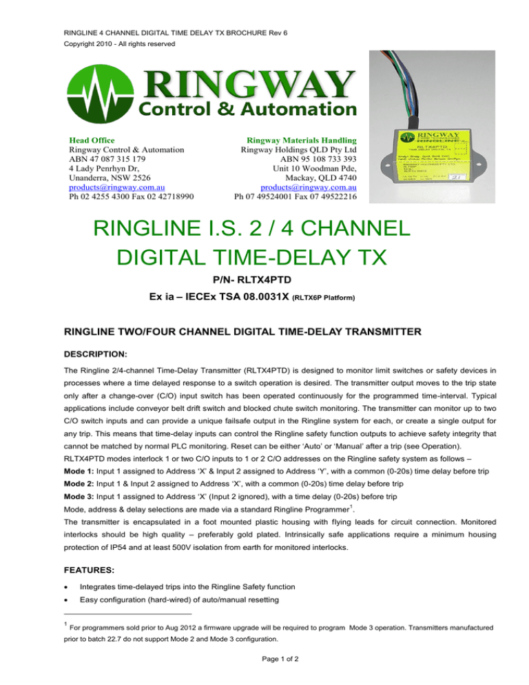
The Ringline 2/4-channel Time-Delay Transmitter (RLTX4PTD) is designed to monitor limit switches or safety devices in
processes where a time delayed response to a switch operation is desired. The transmitter output moves to the trip state
only after a change-over (C/O) input switch has been operated continuously for the programmed time-interval. Typical
applications include conveyor belt drift switch and blocked chute switch monitoring. The transmitter can monitor up to two
C/O switch inputs and can provide a unique failsafe output in the Ringline system for each, or create a single output for
any trip. This means that time-delay inputs can control the Ringline safety function outputs to achieve safety integrity that
cannot be matched by normal PLC monitoring. Reset can be either ‘Auto’ or ‘Manual’ after a trip (see Operation).
RLTX4PTD modes interlock 1 or two C/O inputs to 1 or 2 C/O addresses on the Ringline safety system as follows –
Mode 1: Input 1 assigned to Address ‘X’ & Input 2 assigned to Address ‘Y’, with a common (0-20s) time delay before trip
Mode 2: Input 1 & Input 2 assigned to Address ‘X’, with a common (0-20s) time delay before trip
Mode 3: Input 1 assigned to Address ‘X’ (Input 2 ignored), with a time delay (0-20s) before trip
1
Mode, address & delay selections are made via a standard Ringline Programmer .
The transmitter is encapsulated in a foot mounted plastic housing with flying leads for circuit connection. Monitored
interlocks should be high quality – preferably gold plated. Intrinsically safe applications require a minimum housing
protection of IP54 and at least 500V isolation from earth for monitored interlocks.
FEATURES:
Integrates time-delayed trips into the Ringline Safety function
Easy configuration (hard-wired) of auto/manual resetting
1
For programmers sold prior to Aug 2012 a firmware upgrade will be required to program Mode 3 operation. Transmitters manufactured
prior to batch 22.7 do not support Mode 2 and Mode 3 configuration.
Page 1 of 2
Push button ‘override’ function to facilitate re-alignment work or diagnostic operation (manual reset mode)
Intrinsically Safe (Ex ia I)
Built in surge / lightning protection
Programmable address/es) and time-delay
Dual output mode provides trip discrimination
Single output mode minimises consumption of Ringline addresses
OPERATION:
Trip: While the changeover contacts of a transmitter (Tx) input are tripped the Tx runs a timer for that input. If the inputs
remain tripped for the ‘programmed’ (0 - 20 sec) period the Tx will invert the programmed Ringline address from healthy [A
Ch=On, B Ch=Off] to the tripped state [A Ch=Off, B Ch=On]. If the Ringline address is assigned to control a system
‘Safety Card’, the Safety Function outputs will trip in response. Input recovery prior to tripping resets the delay timer.
Auto Mode: If the Auto input (violet) is tied to Common (black) of a ‘tripped’ transmitter the output Ringline address will
return to ‘healthy’ (1:0) if / when its’ assigned changeover input returns to the healthy state (1:0). Manual Mode: If the
violet wire is not connected to black any trip will ‘latch’ and require a local manual reset effected by the momentary
connection (>1s) of the override input (pink wire) to black. This forces the Ringline address assigned to the tripped input to
the healthy state (1:0) for 2 minutes, allowing time for re-alignment or diagnostics to be performed. Unless the over-ride
input is re-asserted before the 2 minute delay is up the transmitter will revert to normal operation (based on the status of
its’ inputs and the programmed time delay). The operation precludes permanent jamming of the override pushbutton.
PROGRAMMING:
CONFIGURATION MODES – set using Ringline Programmer
PROGRAMMER PARAMETERS
ADD1
ADD2
DELAY
1: Input 1 (Grey-Brown) @ Addr X; Input 2 (Orange-Yellow) @ Addr Y (TWO-IN:TWO-OUT)
X
Y
0...20
2: Input 1 (Grey-Brown) @ Addr X; Input 2 (Orange-Yellow) @ Addr X (TWO-IN: ONE-OUT)*
X
X
0...20
3: Input 1 (Grey-Brown) @ Addr X; Input 2 Disabled (Orange-Yellow) (ONE-IN: ONE-OUT)
X
DISB**
0...20
*A potential hazard may arise if a transmitter intended for a Mode 2 (Two-In One-Out) installation is erroneously programmed for Mode 3 (One-In
One-Out) - i.e. Input 2 (Orange-Yellow) is disabled. Commissioning must confirm that every input controls the safety function as expected!!!
**DISB is located between the highest & lowest address option on the Programmer. If the DISB option is selected for ADD1 then both inputs will be ‘disabled’.
This is a safety measure to ensure that for Mode 3 (One-In One-Out) only Input 1 (GreyBrown) is used.
BRIEF TECHNICAL SPECIFICATIONS:
SIGNAL
RINGLINE 2 WIRE FIELD BUS
Power Supply:
COMMON
7.4Vavg Ringline field bus
DRIFT SWITCH
Inputs:
2 or 1 x voltage-free C/O contacts
Changeover
Switch #1
black
grey
brown
onto the Ringline field bus
green
Com
A
2 or 1 Ringline Addresses, encoded
blue
white
Output:
INPUT 1
Programming Only
Electronic transfer via Ringline
B
Programmer
RLTX4PTD
Changeover
Switch #2
black
orange
yellow
Operating Temperature Range:
Com
C
-30 → +75 ºC
INPUT 2
D
Dimensions:
Link in = Auto, No Link = Manual
violet
black
pink
Configuration:
Auto
70 (w tabs) / 50 (w body) x 30(h) x
Com
25(d) mm
Ovr
Override
Ø3mm mounting holes - 60mm apart
Page 2 of 2

