Technical Data Delay Timer with 2-wire Output WTS-4181
advertisement

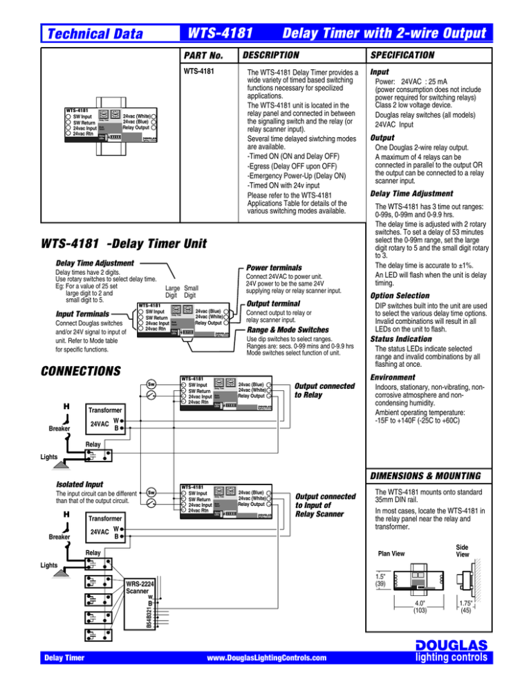
WTS-4181 Technical Data DESCRIPTION PART No. WTS-4181 Delay Time Mode Select Status LEDs The WTS-4181 Delay Timer provides a wide variety of timed based switching functions necessary for specilized applications. The WTS-4181 unit is located in the relay panel and connected in between the signalling switch and the relay (or relay scanner input). Several time delayed siwtching modes are available. -Timed ON (ON and Delay OFF) -Egress (Delay OFF upon OFF) -Emergency Power-Up (Delay ON) -Timed ON with 24v input Please refer to the WTS-4181 Applications Table for details of the various switching modes available. 24vac (White) 24vac (Blue) Relay Output On WTS-4181 SW Input SW Return 24vac Input 24vac Rtn Delay Timer with 2-wire Output WTS-4181 -Delay Timer Unit Delay Time Adjustment Connect Douglas switches and/or 24V signal to input of unit. Refer to Mode table for specific functions. Output terminal 24vac (Blue) 24vac (White) Relay Output Delay Time Mode Select Status LEDs Connect output to relay or relay scanner input. Range & Mode Switches Use dip switches to select ranges. Ranges are: secs. 0-99 mins and 0-9.9 hrs Mode switches select function of unit. Sw WTS-4181 SW Input SW Return 24vac Input 24vac Rtn Transformer Input Power: 24VAC : 25 mA (power consumption does not include power required for switching relays) Class 2 low voltage device. Douglas relay switches (all models) 24VAC Input Output One Douglas 2-wire relay output. A maximum of 4 relays can be connected in parallel to the output OR the output can be connected to a relay scanner input. Delay Time Adjustment The WTS-4181 has 3 time out ranges: 0-99s, 0-99m and 0-9.9 hrs. The delay time is adjusted with 2 rotary switches. To set a delay of 53 minutes select the 0-99m range, set the large digit rotary to 5 and the small digit rotary to 3. The delay time is accurate to ±1%. An LED will flash when the unit is delay timing. Option Selection DIP switches built into the unit are used to select the various delay time options. Invalid combinations will result in all LEDs on the unit to flash. Status Indication The status LEDs indicate selected range and invalid combinations by all flashing at once. Environment Delay Time Mode Select Status LEDs 24vac (Blue) 24vac (White) Relay Output Output connected to Relay On CONNECTIONS Breaker Connect 24VAC to power unit. 24V power to be the same 24V supplying relay or relay scanner input. Large Small Digit Digit WTS-4181 SW Input SW Return 24vac Input 24vac Rtn Input Terminals H Power terminals On Delay times have 2 digits. Use rotary switches to select delay time. Eg: For a value of 25 set large digit to 2 and small digit to 5. SPECIFICATION 24VAC W B Indoors, stationary, non-vibrating, noncorrosive atmosphere and noncondensing humidity. Ambient operating temperature: -15F to +140F (-25C to +60C) Relay Lights DIMENSIONS & MOUNTING The input circuit can be different than that of the output circuit. H Breaker Sw Transformer WTS-4181 SW Input SW Return 24vac Input 24vac Rtn Delay Time Mode Select Status LEDs On Isolated Input 24vac (Blue) 24vac (White) Relay Output Output connected to Input of Relay Scanner 24VAC W B Relay The WTS-4181 mounts onto standard 35mm DIN rail. In most cases, locate the WTS-4181 in the relay panel near the relay and transformer. Side View Plan View Lights 1.5" (39) WRS-2224 Scanner w B B54B321 4.0" (103) Delay Timer www.DouglasLightingControls.com 1.75" (45) Time-out Sw ON Closed 24v input enables the time-out function. Sw ON Closed Option 99m 99s 24 V Input 9.9h Douglas Sw Input Mode Technical Data WTS-4181 Delay Timer with 2-wire Output Range Output Only 1 Range sw on to select this mode. Range sw on selects range ON, then Delay OFF ON, then Delay OFF with Flick warn • Lights are switched ON; Time-Out mode is used to automatically switch lights OFF after a set time period.\ • The 24V input must be closed (24vac applied) to "enable" the Time-Out mode. Use this feature to enable time-out switching only during unoccupied periods. Switch ON, Delay OFF Reset with On Signal Sw OFF, Cancel Delay OFF Removal of Enable Input Off with Flick warn Power During 5 min flick delay, the first signal from the sw cancels the impending off. Sw Input On Off Enable Close Input Open Output delay t delay t delay t On Off Egress Sw OFF Closed 24v input enables the egress function. Sw OFF Closed delay t delay t Only 1 Range sw on to select this mode. Range sw on selects range 5 min flick delay Delay OFF Delay OFF with Flick Warn • Lights are switched OFF; Egress mode delays the lights OFF signal to permit egress. • The enable input must be closed (24vac applied) for the Egress (Delay-OFF) mode to work. Switch OFF, Delay OFF Cancel with OFF Signal Sw ON, Cancel Delay Off Removal of Enable Input Delay OFF with flick Power During 5 min flick delay, the first signal from the sw cancels the impending off. Sw Input On Off Enable Close Open Input On Output Off delay t delay t delay t delay t 5 min flick delay delay t Emergency Power-up no Sw Closed no Sw Closed All Range Sws on to select this mode. Operates in 0-99s range only. Delay ON Delay ON with Repeat • Power is lost and emergency power is brought on line. A remote contact can be used to signal the system to switch lights ON. • To ensure remote contact has effect, use repeat option. If no remote contact available, use panel 24vac power without repeat. • The delay time should be sufficient (3 sec or more) to permit the lighting system controls to come "on-line". Input ON, Delay ON Power Up, Delay ON Input OFF, Cancel Delay ON Input ON, Delay ON with Repeat Power Sw Input On Off Enable Close Open Input On Output Off Switch input has no effect Switch input has no effect delay t Timed ON by 24V Input Switch input has no effect delay t no Sw Closed no Sw Closed Switch input has no effect delay t delay t Contact input 0-99m range. Contact input 0-9.9h range. delay t delay t ON, then Delay OFF ON, then Delay OFF with Flick Warn • Switch input is inactive, the 24V input controls the output; Use to interface contact closures to a Douglas relay or system. Power Sw Input On Off Contact Close Open Input Output On Off Delay Timer Input ON, ON & Delay OFF Input OFF before delay over Input ON, Delay OFF with flick Switch input has no effect Switch input has no effect Switch input has no effect delay t delay t delay t Open after delay has no effect 5 min flick delay www.DouglasLightingControls.com Input OFF, Delay OFF / Input ON, Delay ON This mode only: All off, 99s range delay t delay t (in sec) delay t (in min)


