CH-40250
codes and standards
rev. 1,
• UL listed to Standard 924
• UL damp location listing option 32°F (0°C) to
104°F (40°C)
• IBC, BOCA, and OSHA illumination standard
• NFPA 101 (Life Safety Code)
• NFPA 70 (National Electric Code)
• City of Chicago approved
• New York City approved
construction
• Enclosure is constructed of 18 gauge steel with a
20 gauge cover with a white corrosion resistant,
epoxy powder coat finish.
• Nine standard and custom colors available, consult
factory.
installation
• Easily mounted with key hole slots or optional
mounting plates.
• All housings have six available 1/2" conduit
knockouts.
• 1/4" toggle bolts are recommended for installation.
electronics
• All models include an on-board IR receiver for use
with the optional hand-held remote (ICIR).
• (optional) self-testing electronics
The diagnostic/charging platform with optional
self-testing mode automatically runs a one minute
self-test every 30 days and a 30 minute test on the
sixth and twelfth month in accordance with NFPA
101.
A one minute or 90 minute test may be initiated via
the push to test switch on the unit or by activating
the appropriate test command on the optional IR
test device.
• operating temperature range
Standard Location: 65°F (19°C) to 85°F (30°C).
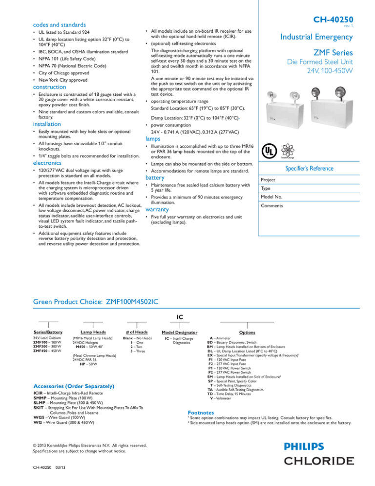
Industrial Emergency
ZMF Series
Die Formed Steel Unit
24V, 100-450W
Damp Location: 32°F (0°C) to 104°F (40°C).
• power consumption
24 V - 0.741 A (120 VAC), 0.312 A (277 VAC)
lamps
• Illumination is accomplished with up to three MR16
or PAR 36 lamp heads mounted on the top of the
enclosure.
• Lamps can also be mounted on the side or bottom.
• Accommodations for remote lamps are standard.
• 120/277 VAC dual voltage input with surge
protection is standard on all models.
battery
• All models feature the Intelli-Charge circuit where • Maintenance free sealed lead calcium battery with
the charging system is microprocessor driven
5 year life.
with software embedded diagnostic routine and
• Provides a minimum of 90 minutes emergency
temperature compensation.
illumination.
• All models include brownout detection, AC lockout,
low voltage disconnect, AC power indicator, charge warranty
status indicator, audible user-interface controls,
• Five full year warranty on electronics and unit
visual LED system fault indicator, and tactile push(excluding lamps).
to-test switch.
• Additional equipment safety features include
reverse battery polarity detection and protection,
and reverse utility power detection and protection.
Intelli-Charge
Specifier’s Reference
Project
Type
Model No.
Comments
Green Product Choice: ZMF100M4502IC
IC
Series/Battery
Lamp Heads
# of Heads
24 V, Lead Calcium
ZMF100 – 100 W
ZMF300 – 300 W
ZMF450 – 450 W
(MR16 Metal Lamp Heads)
24 VDC Halogen
M450 – 50 W, 40°
Blank – No Heads
1 – One
2 – Two
3 – Three
(Metal Chrome Lamp Heads)
24 VDC PAR 36
HP – 50 W
Accessories (Order Separately)
ICIR – Intelli-Charge Infra-Red Remote
SMMP – Mounting Plate (100 W)
SLMP – Mounting Plate (300 & 450 W)
SKIT – Strapping Kit For Use With Mounting Plates To Affix To
Columns, Poles and I-beams
WG5 – Wire Guard (100 W)
WG – Wire Guard (300 & 450 W)
© 2013 Koninklijke Philips Electronics N.V. All rights reserved.
Specifications are subject to change without notice.
CH-40250 03/13 Options
Model Designator
IC – Intelli-Charge
Diagnostics
A – Ammeter
BD – Battery Disconnect Switch
BM – Lamp Heads Installed on Bottom of Enclosure
DL – UL Damp Location Listed (0°C to 40°C)
EX – Special Input Transformer (specify voltage & frequency)1
F1 – 120 VAC Input Fuse
F2 – 277 VAC Input Fuse
P1 – 120 VAC Power Switch
P2 – 277 VAC Power Switch
SM – Lamp Heads Installed on Side of Enclosure2
SP – Special Paint, Specify Color
T – Self-Testing Diagnostics
TA – Audible Self-Testing Diagnostics
TD – Time Delay, 15 Minutes
V – Voltmeter
Footnotes
1
2
Some option combinations may impact UL listing. Consult factory for specifics.
Side mounted lamp heads option (SM) are not installed onto the enclosure at the factory.
CH-40250
options
ZMF Die Formed Steel Unit 24V, 100-4500W
rev. 1,
• P2 – The AC power switch option includes a toggle switch electrically
connected to the primary of the input transformer limited to 277 VAC
circuits. This option allows for opening the utility feed to the equipment for
servicing or maintenance.
• T – The self-testing option enables a periodic self-test of the equipment
where a test routine is established to perform a one-minute test every
thirty days with a 30 minute test performed on the sixth and twelfth month
in accordance with NFPA 101. Equipment readiness faults are indicated with
a visual LED display.
• TA – The audible self-testing option enables a periodic self-test of the
equipment where a test routine is established to perform a one-minute
test every thirty days with a 30 minute test performed on the sixth and
twelfth month in accordance with NFPA 101. Equipment readiness faults are
indicated with a visual LED display and an audible alarm.
• TD – The time delay circuit causes the emergency lighting equipment to
remain under battery power for a period of 15 minutes after the utility
power has been restored.
• V – The voltmeter option includes an analog meter electrically connected
between the battery and lamp load for visual reference and indication
of the battery terminal voltage when the equipment is operating in the
emergency mode.
• A – The ammeter option includes an analog meter electrically connected to
the charging circuit for visual reference and indication of the current level
being delivered to the battery.
• BD – The battery disconnect switch allows for the electrical switching
between the battery and the connected load (lamp heads) whether they
be directly mounted to the equipment or installed as remote lamp heads.
The switch will be located internally to the equipment and is not made
accessible other to those who perform maintenance on the equipment.
• DL – Damp location listed products include various levels of corrosion
protection on printed circuit board assemblies and other metallic parts.
Environmental testing throughout a range of ambient temperature and 88%
relative humidity.
• EX – The special input transformer option allows for input voltage and
frequencies beyond the standard 120/277 VAC, 60 Hz input.
• F1 – The AC fuse option includes an in-line fuse on the primary winding
of the input transformer for additional electronic protection against utility
surges or spikes limited to 120 VAC circuits.
• F2 – The AC fuse option includes an in-line fuse on the primary winding
of the input transformer for additional electronic protection against utility
surges or spikes limited to 277 VAC circuits.
• P1 – The AC power switch option includes a toggle switch electrically
connected to the primary of the input transformer limited to 120 VAC
circuits. This option allows for opening the utility feed to the equipment for
servicing or maintenance.
dimensions
100 W
300, 450 W
14.0”
(35.56cm)
16.0”
(40.64cm)
9.1”
(23.11cm)
13.4”
(34.04cm)
11.0”
(27.94cm)
7.4”
(18.8cm)
18.2”
(46.23cm)
9.4”
(23.88cm)
performance
Meets Life Safety Code illumination standard; average of 1.0 FC, no point
less than 0.1 FC, max to min ratio of 40:1. Assumes open space with no
obstructions, mounting height: 9' and reflectances: 80/50/20. Analysis based
on independently tested photometrics.
Wall mounted 9’ AFF, 24 V 50 W MR16 Lamps
1 FC Average
9 ft.
1.5
2.0
1.4
1.5
2.4
2.7
4.7
3.9
1.3
.8
3.5
2.7
.7
1.7
1.3
1.7
1.3
.7
.7
3.6
2.6
1.3
4.7
3.9
1.4
Test No.: M450
Average initial footcandles at floor = 1.81
Maximum initial footcandles at floor = 6.4
Minimum initial footcandles at floor = 0.2
Maximum to minimum ratio = 32.00
2.5
2.8
1.3
1.3
1.7
.7
.6
.9
.5
60 ft.
.4
.5
.4
.3
.4
.5
.4
.5
.6
.6
.9
1.2
1.3
1.7
2.5
2.5
2.7
1.3
4.7
3.9
.8
3.5
2.7
.7
1.7
1.3
.8
1.7
1.3
.8
3.6
2.6
4.7
4.0
1.3
1.5
2.5
2.8
1.4
1.5
2.0
12 ft.
© 2013 Koninklijke Philips Electronics N.V. All rights reserved.
Specifications are subject to change without notice.
Philips Lighting Company
200 Franklin Square Drive
Somerset, NJ 08873
Phone: 855-486-2216
Philips Lighting Company
281 Hillmount Road
Markham ON, Canada L6C 2S3
Phone: 800-668-9008
CH-40250 03/13 www.philips.com/luminaires
www.philips.com/luminaires


