V-Brake tail light flasher installation instructions
Parts4PowerToys is proud to offer a custom designed programmable V-Brake tail light brake
flasher module. V-Brake module is a micro processor designed tail brake light flasher that provides 37
user programmable flashing modes with user selectable brake application re-application delays. Once
initially trigger, the user can select 0,15 and 30 seconds delays before the flasher will re-flash the brake
tail lights. Installation takes less that 15 minutes and the kit comes complete with all the necessary parts
for installation.
Step1:
Remove the seat on your Harley Davidson and locate the wiring harness going to the rear fender
.Once located, test each wire to see which one applies 12 Volts to the the rear brake light (usually the
RED wire with YELLOW strip on most models). In the illustration figure A below on a FLHTRI
(Road Glide), the red wire with yellow strip, carries the 12 volts to the brake tail light assembly (wire
color may differ on different models). Cut the wire to allow connecting the V-Brake flasher module.
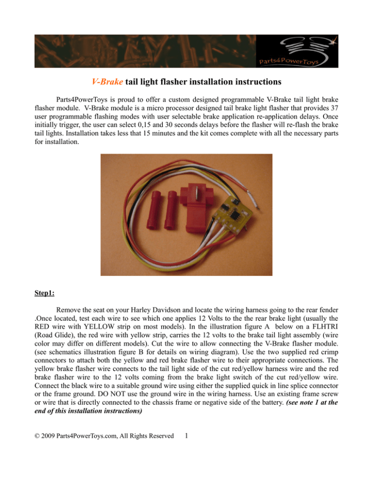
(see schematics illustration figure B for details on wiring diagram). Use the two supplied red crimp
connectors to attach both the yellow and red brake flasher wire to their appropriate connections. The
yellow brake flasher wire connects to the tail light side of the cut red/yellow harness wire and the red
brake flasher wire to the 12 volts coming from the brake light switch of the cut red/yellow wire.
Connect the black wire to a suitable ground wire using either the supplied quick in line splice connector
or the frame ground. DO NOT use the ground wire in the wiring harness. Use an existing frame screw
or wire that is directly connected to the chassis frame or negative side of the battery. (see note 1 at the
end of this installation instructions)
© 2009 Parts4PowerToys.com, All Rights Reserved
1
Figure A
Figure B
Step 2:
The V-Brake flasher module has 37 modes (see table figure C). Use the flasher value white
wires to switch the modes. In order to switch the modes, follow the steps below.
1. Push the brake pedal so the brake light is illuminated.
2. Short and disconnect the white wire. The V-Brake flasher module will switch to the next mode
and flash the the brake light according to the next selected pattern. A small green led will flash
on the V-Brake module in sync with the brake light to help determine the flash mode. Continue
shorting and disconnecting the white wires to switch to the next flash mode until the desired
mode is reached. (refer to the flash mode table in figure C).
3. Mode 37 is the off mode. In this mode the flashing function is turned off and the brake light will
function in it's normal on/off braking operation.
© 2009 Parts4PowerToys.com, All Rights Reserved
2
4. Once mode 37 is reached, the next mode selection sets the mode back into the #1 flash mode
and so on. Refer to the table in Figure C below.
5. Tape and secure all connections to ensure that the module and connections do not brake loose
due to vibration and/or rubbing against other parts.
Figure C
Note 1: These pictures are for illustration only and may not accurately represent your particular
Harley Davidson model. Refer to the schematic diagram in figure B for more details on wire
connections.
© 2009 Parts4PowerToys.com, All Rights Reserved
3


