SerieS 94r Rotary DIP Switches
advertisement
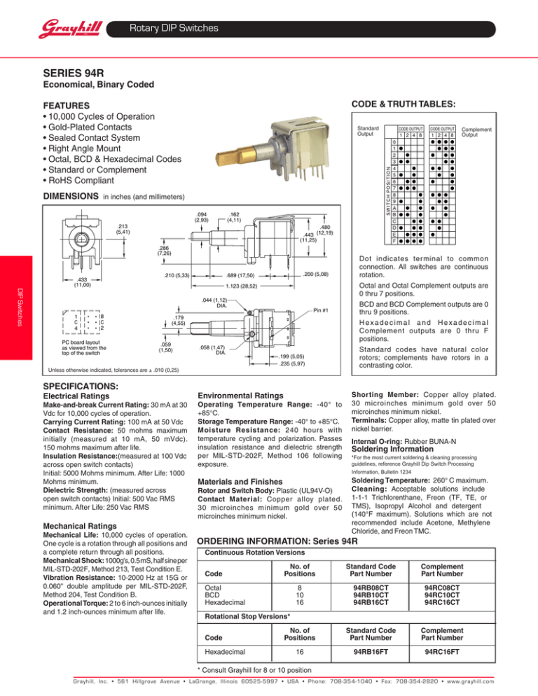
Rotary DIP Switches Series 94R Economical, Binary Coded Code & Truth Tables: Features • 10,000 Cycles of Operation • Gold-Plated Contacts • Sealed Contact System • Right Angle Mount • Octal, BCD & Hexadecimal Codes • Standard or Complement • RoHS Compliant S W I T C H P O S I T I O N DIMENSIONS Standard Output in inches (and millimeters) .094 (2,93) .162 (4,11) .213 (5,41) .480 .443 (12,19) (11,25) .286 (7,26) .210 (5,33) .433 (11,00) DIP Switches 1.123 (28,52) .044 (1,12) DIA. 1 C 4 8 C 2 PC board layout as viewed from the top of the switch Pin #1 .179 (4,55) .059 (1,50) .058 (1,47) DIA. .199 (5,05) .235 (5,97) Unless otherwise indicated, tolerances are ± .010 (0,25) Specifications: Electrical Ratings Make-and-break Current Rating: 30 mA at 30 Vdc for 10,000 cycles of operation. Carrying Current Rating: 100 mA at 50 Vdc Contact Resistance: 50 mohms maximum initially (measured at 10 mA, 50 mVdc). 150 mohms maximum after life. Insulation Resistance:(measured at 100 Vdc across open switch contacts) Initial: 5000 Mohms minimum. After Life: 1000 Mohms minimum. Dielectric Strength: (measured across open switch contacts) Initial: 500 Vac RMS minimum. After Life: 250 Vac RMS Environmental Ratings Operating Temperature Range: -40° to +85°C. Storage Temperature Range: -40° to +85°C. Moisture Resistance: 240 hours with temperature cycling and polarization. Passes insulation resistance and dielectric strength per MIL-STD-202F, Method 106 following exposure. 1 2 4 8 Complement Output 0 1 2 3 4 5 6 7 8 9 A B C D E F Shorting Member: Copper alloy plated. 30 microinches minimum gold over 50 microinches minimum nickel. Terminals: Copper alloy, matte tin plated over nickel barrier. Internal O-ring: Rubber BUNA-N Soldering information *For the most current soldering & cleaning processing guidelines, reference Grayhill Dip Switch Processing Information, Bulletin 1234 Materials and Finishes Rotor and Switch Body: Plastic (UL94­V-O) Contact Material: Copper alloy plated. 30 microinches minimum gold over 50 microinches minimum nickel. Mechanical Ratings Mechanical Life: 10,000 cycles of operation. One cycle is a rotation through all positions and a complete return through all positions. Mechanical Shock: 1000g's, 0.5 mS, half sine per MIL-STD-202F, Method 213, Test Condition E. Vibration Resistance: 10-2000 Hz at 15G or 0.060" double amplitude per MIL-STD-202F, Method 204, Test Condition B. Operational Torque: 2 to 6 inch-ounces initially and 1.2 inch-ounces minimum after life. CODEOUTPUT 1 2 4 8 Dot indicates terminal to common connection. All switches are continuous rotation. Octal and Octal Complement outputs are 0 thru 7 positions. BCD and BCD Complement outputs are 0 thru 9 positions. Hexadecimal and Hexadecimal Complement outputs are 0 thru F positions. Standard codes have natural color rotors; complements have rotors in a contrasting color. .200 (5,08) .689 (17,50) CODEOUTPUT Soldering temperature:260°Cmaximum. Cleaning: Acceptable solutions include 1-1-1 Trichlorenthane, Freon (TF, TE, or TMS), Isopropyl Alcohol and detergent (140°F maximum). Solutions which are not recommended include Acetone, Methylene Chloride,andFreonTMC. ORDERING INFORMATION: Series 94R Continuous Rotation Versions No. of Standard Code Complement CodePositionsPart NumberPart Number Octal BCD Hexadecimal 8 10 16 94RB08CT 94RB10CT 94RB16CT 94RC08CT 94RC10CT 94RC16CT Rotational Stop Versions* No. of Standard Code Complement CodePositionsPart NumberPart Number Hexadecimal 16 94RB16FT 94RC16FT * Consult Grayhill for 8 or 10 position Grayhill, Inc. • 561 Hillgrove Avenue • LaGrange, Illinois 60525-5997 • USA • Phone: 708-354-1040 • Fax: 708-354-2820 • www.grayhill.com
![1S2 (Timoney) Tutorial sheet 12 [February 11 – 15, 2008] Name: Solutions](http://s2.studylib.net/store/data/011011726_1-e01c0f9d2e7017bbc750b30100b0c2cf-300x300.png)
