Rack Installation Instructions
Review the documentation that comes with the rack cabinet for safety and cabling information. Before
you install the server in a rack cabinet, review the following guidelines:
v Make sure that the room air temperature is below 35°C (95°F).
v Do not block any air vents; usually 15 cm (6 in.) of space provides proper airflow.
v Do not leave open spaces above or below an installed server in your rack cabinet. To help prevent
damage to server components, always install a blank filler panel to cover the open space and to help
ensure proper air circulation.
v Install the server only in a rack cabinet with perforated doors.
v Plan the device installation starting from the bottom of the rack cabinet.
v Install the heaviest device in the bottom of the rack cabinet.
v Do not extend more than one device out of the rack cabinet at the same time.
v Remove the rack doors and side panels to provide easier access during installation.
v Connect the server to a properly grounded outlet.
v Do not overload the power outlet when you install multiple devices in the rack cabinet.
v Install the server in a rack cabinet that meets the following requirements:
– Minimum depth of 49 mm (1.9 in.) between the front mounting flange and inside of the front door
– Minimum depth of 470 mm (18.5 in.) and maximum depth of 813 mm (32 in.) between the front and
rear mounting flanges.
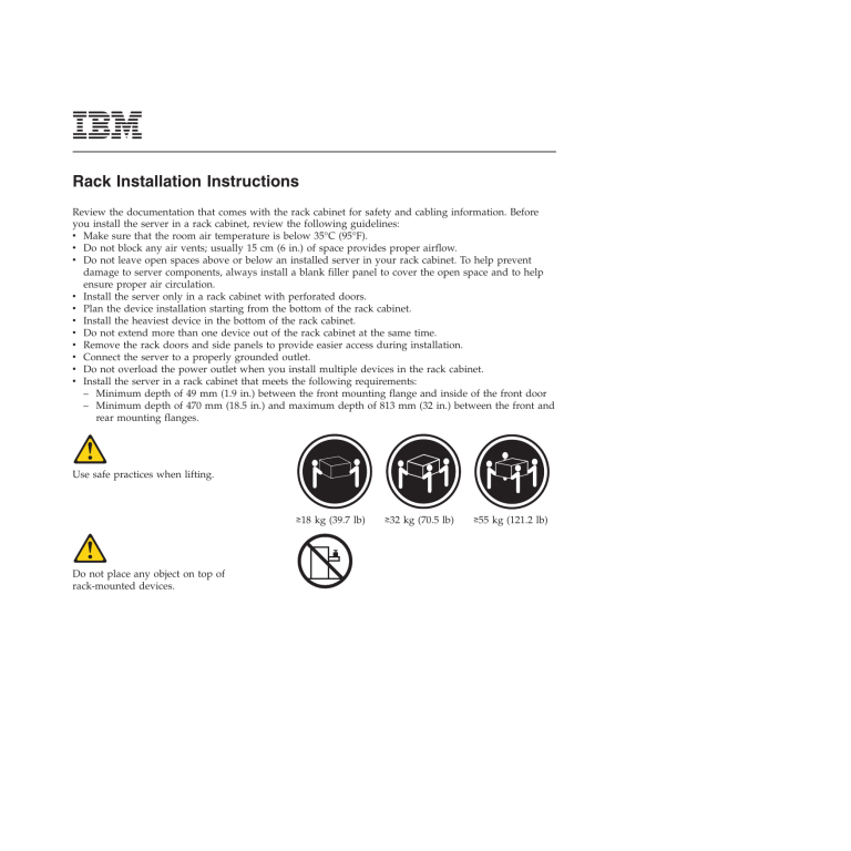
Use safe practices when lifting.
≥18 kg (39.7 lb)
Do not place any object on top of
rack-mounted devices.
≥32 kg (70.5 lb)
≥55 kg (121.2 lb)
The following illustration shows the items that you need to install the server in the rack cabinet. If any
items are missing or damaged, contact your place of purchase.
Note: Some items come with the server, not in the rack installation kit.
Cable straps
(5)
Rails (2)
Rear of rail
Shipping bracket screws (2)
Shipping brackets (2)
Cable ties
(5)
M6 screws
(8)
Cage nuts
(8)
Clip nuts
(8)
Front of rail
Use cage nuts for rack cabinets with square holes, use clip nuts for rack cabinets with round holes, and
use your own rack screws for rack cabinets with tapped-holes. If your rack cabinet requires cage nuts,
use a cage-nut-insertion tool or a flat-blade screwdriver to install them.
Cage
nuts
Cage
nuts
2
Clip
nuts
To install the server in a rack cabinet, complete the following steps:
1
2
Rear
Front
U
U
U
U
U
U
U
U
Rail
adjustment
latch
U
U
U
U
Optional screw for vibration-prone areas
Select an available U space in the rack cabinet to
install the server. If the rack cabinet has round holes
or square holes, install cage nuts or clip nuts in the
top and bottom holes of the selected U space on
each rear rack flange. Then, install a cage nut or
clip nut in the bottom hole of the U space on each
front rack flange.
Note: If you move the rack cabinet with the server
installed, or if the rack cabinet is installed in a
vibration-prone area, install a cage nut or clip nut
in the top hole of the U space on each front rack
flange.
If the depth of the rack cabinet requires it, adjust
the length of the rail by lifting the rail-adjustment
latch and then extending the rail to the depth you
want.
3
3
4
Mounting pin
and nut
If the rack cabinet has round holes, remove the
round nut from the mounting pin on the front of
the rail. If the rack cabinet has tapped holes, use a
Phillips screwdriver to unscrew and remove the
mounting pin and nut assembly from the rail.
Front
U
Mounting pin
(and nut if the rack cabinet
has square holes)
While you are standing at the front of the rack
cabinet, hook the mounting pin (and the nut, if the
rack cabinet has square holes) into the middle hole
of the U space on the front of the rack cabinet.
Make sure that the rail bracket is on the outside of
the rack flange. (If you are installing the server in a
rack cabinet with tapped holes, this step does not
apply.)
Extend the rear of the rail so that the rail bracket is
on the outside of the rack flange.
4
5
6
M6
screws
Front
Front
Installed shipping
bracket
Shipping
bracket (2)
U
U
M6
screw
Rear
Rear
Secure the rear of the rail with two M6 screws and
secure the front of the rail with one M6 screw as
shown.
If you are installing the server in a rack cabinet
with tapped holes, you must hold the rail in place
while you secure the rail with the M6 screws.
Repeat steps 2 through 5 for the other rail.
Shipping
bracket screw (2)
If you move the rack cabinet with the server
installed, or if the rack cabinet is installed in a
vibration-prone area, install the shipping brackets
on the server rear chassis:
1. Remove the cover from the server:
a. Loosen the captive screw on the rear of the
cover.
b. Disengage the tabs on the sides of the cover
from the matching slots on the sides of the
chassis.
c. Slide the cover toward the rear of the server,
and lift the cover off the server.
2. Align the right shipping bracket with the rear of
the server so that the notched end faces away
from the rear of the server1. Make sure that
the right (R) or left (L) marking on the bracket
faces the server chassis.
3. Insert the two tabs on the shipping bracket into
the two holes in the rear of the server chassis
1 and align the screw hole in the bracket with
the screw hole in the chassis.
4. Secure the bracket with one shipping bracket
screw 2.
5. Repeat the steps for the other shipping bracket.
6. Replace the server cover and tighten the captive
screw.
5
7
8
M6
screws (2)
Lift the server onto the rails and slide the server to
the rear of the rack cabinet until the front rack
latches click closed.
If you move the rack cabinet with the server
installed, or if the rack cabinet is installed in a
vibration-prone area, secure the server to the rack
cabinet with one M6 screw in the top hole on each
front rail bracket.
Secure any cables with the cable straps and cable ties that come with the rail kit.
To remove the server from the rack cabinet, press down on the rack latches and slide the server from the
rack cabinet. Store this information with the server documentation for future use.
6
7
First Edition (September 2006)
IBM is a trademark of International Business Machines Corporation in the United States, other countries, or both.
© Copyright International Business Machines Corporation 2006. All rights reserved.
US Government Users Restricted Rights – Use, duplication or disclosure restricted by GSA ADP Schedule Contract
with IBM Corp.
(1P) P/N: 42D8412


