IL9270N DTMF signal receiver
advertisement

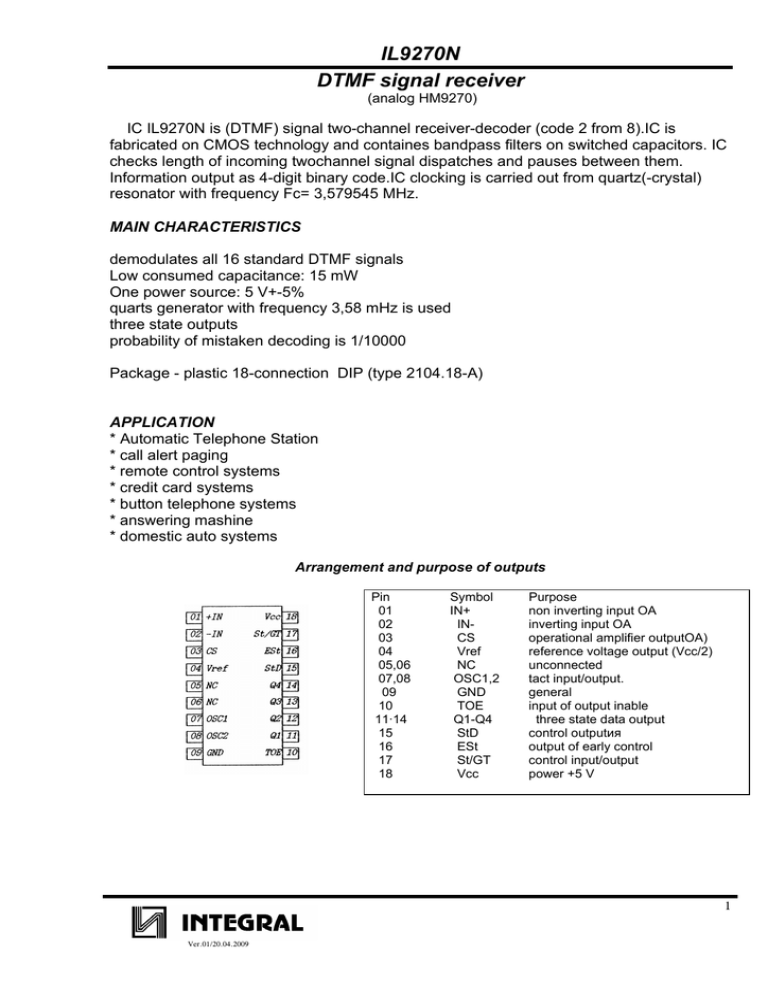
IL9270N DTMF signal receiver (analog HM9270) IC IL9270N is (DTMF) signal two-channel receiver-decoder (code 2 from 8).IС is fabricated on CМОS technology and containes bandpass filters on switched capacitors. IC checks length of incoming twochannel signal dispatches and pauses between them. Information output as 4-digit binary code.IC clocking is carried out from quartz(-crystal) resonator with frequency Fc= 3,579545 МHz. MAIN CHARACTERISTICS demodulates all 16 standard DTMF signals Low consumed capacitance: 15 mW One power source: 5 V+-5% quarts generator with frequency 3,58 mHz is used three state outputs probability of mistaken decoding is 1/10000 Package - plastic 18-connection DIP (type 2104.18-А) APPLICATION * Аutomatic Тelephone Station * call alert paging * remote control systems * credit card systems * button telephone systems * answering mashine * domestic auto systems Arrangement and purpose of outputs Pin 01 02 03 04 05,06 07,08 09 10 11·14 15 16 17 18 Symbol IN+ INCS Vref NC OSC1,2 GND TOE Q1-Q4 StD ESt St/GT Vcc Purpose non inverting input ОA inverting input ОA operational amplifier outputОA) reference voltage output (Vcc/2) unconnected tact input/output. general input of output inable three state data output control outputия output of early control control input/output power +5 V 1 Ver.01/20.04.2009 IL9270N Block-diagram IN+ IN- High Group Filter Two-tone input filter Amplifier Digital detec tor OSC2 Reference voltage Reference voltage generator Tact Generator Q3 Amplifier Offset voltage OSC1 Output cascascade Q1 Q2 Q4 High Group Filter CS Code transformer Vc c Gnd Control Logic Vref St/Gt Est StD TOE Reference table of received DTMF signal and code under formation Low group frequency, Hz 697 697 697 770 770 770 852 852 852 941 941 941 697 770 852 941 high group frequency, Hz 1209 1336 1477 1209 1336 1477 1209 1336 1477 1209 1336 1477 1633 1633 1633 1633 code under formation Q4 0 0 0 0 0 0 0 1 1 1 1 1 1 1 1 0 Q3 0 0 0 1 1 1 1 0 0 0 0 1 1 1 1 0 Q2 0 1 1 0 0 1 1 0 0 1 1 0 0 1 1 0 Q1 1 0 1 1 1 0 1 0 1 0 1 0 1 0 1 IС IL9270 connection scheme 2 Ver.01/20.04.2009 IL9270N DC ELECTRICAL CHARACTERISTICS(VCC = 5 V ± 5%, TA = +25°C) Symbol Parameter Test Conditions Guaranteed Limits Min Typ Unit Max VCC Supply Voltage 4.75 5.25 V ICC Supply Current 9.0 mA ISO Maximum Pull Up (Source) Current OE = 0 V 24 μA IOL Minimum Output-Low (Sink) Current VOUT =0.4 V 0.8 mA IOH Minimum Output-High (Source) Current VOUT =4.6 V 0.35 mA VTSt Steering Threshold Voltage RIN Input Impedance (Signal Inputs 1,2) @ 1 KHz 8 VREF Output Voltage No Load 2.4 AVOL DC Open Loop Voltage Gain 65 dB ROR Output Resistance 10 kΩ 3.0 2.2 2.5 V MΩ 2.8 V AC ELECTRICAL CHARACTERISTICS (VCC = 5.0 V, TA =+25°C, FCLK = 3.579545 MHz) Parameter Guaranteed Limits Min Typ Unit Notes Max SIGNAL CONDITION Valid Input Signal MIN Level (each tone of composite signal) MAX 27.5 mVRMS 883 m VRMS ±1.5 Freq. Deviation Accept Limit % ±3.5 Freq. Deviation Reject Limit Third Tone Tolerance % -16 Dial Tone Tolerance 18 dB 22 TIMING REQUIREMENTS (VCC = 5.0 V, TA = +25°C, FCLK = 3.579545 Mhz) Symbol Parameter Guaranteed Limits Notes Min Max Unit tDP Tone Present Detection Time 5 14 ms tDA Tone Absent Detection Time 0.5 8.5 ms tREC Maximum Tone Duration Accept 40 ms tREC Minimum Tone Duration Reject tID Acceptable Interdigit Pause tDO Rejectable Interdigit Pause 20 ms 40 20 (User Adjustable) ms Refer to “Guard Time ms Adjustment 3 Ver.01/20.04.2009 IL9270N Time diagram 4 Ver.01/20.04.2009


