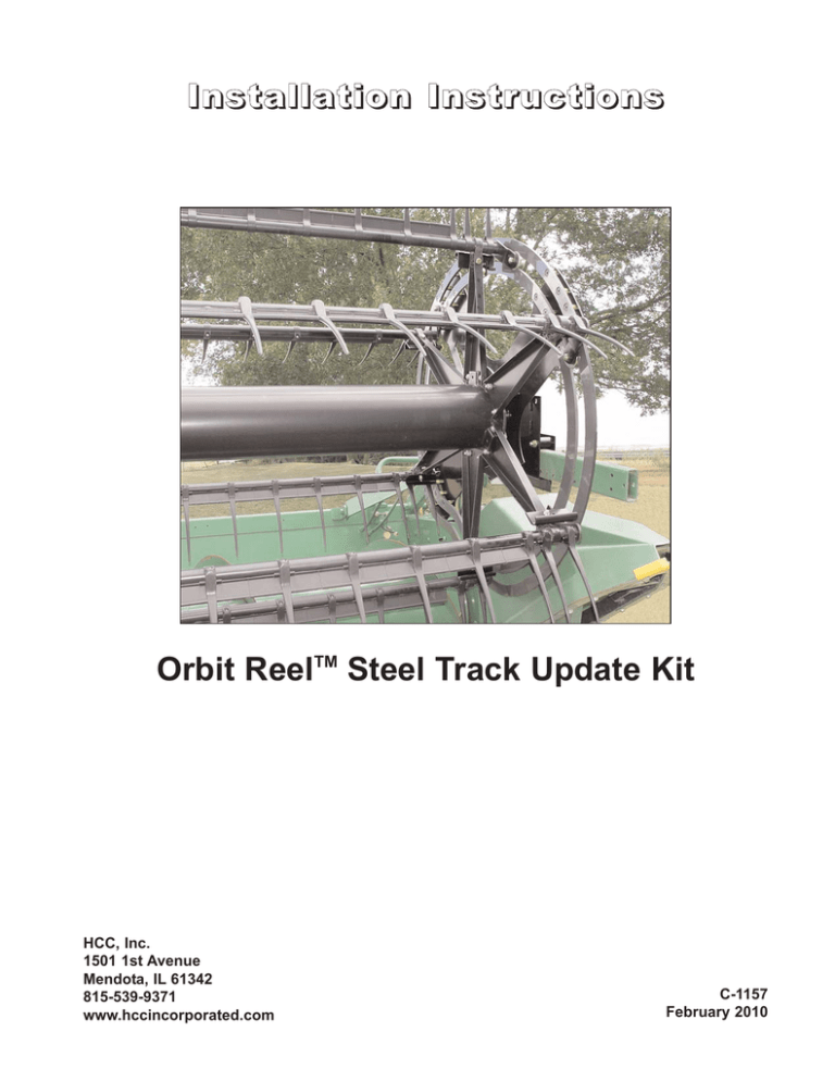
Orbit Reel Steel Track Update Kit Installation Instructions
advertisement

Installation Instructions Orbit ReelTM Steel Track Update Kit HCC, Inc. 1501 1st Avenue Mendota, IL 61342 815-539-9371 www.hccincorporated.com C-1157 February 2010 Safety Alert Symbols Safety The safety alert triangle means Attention! Become Alert! Your Safety is Involved. Most work related accidents are caused by failure to observe basic safety rules or precautions. An accident can often be avoided by recognizing potentially hazardous situations before an accident occurs. As you install the Orbit ReelTM update kit, you must be alert to potential hazards. You should also have the necessary training, skills, and tools to perform this installation properly. Hazards are identified by the “Safety Alert Symbol” and followed by a signal word such as “DANGER”, “WARNING”, or “CAUTION”. DANGER Improper installation of this kit could cause the reel to function incorrectly, resulting in a dangerous situation that could result in injury or death. DANGER: Indicates an imminently hazardous situation which, if not avoided, will result in death or serious injury. This signal word is limited to the most extreme situations. Do not begin the installation of this kit until you read and understand the information contained in this supplement, as well as the OEM information provided by the manufacturer of the combine/header. WARNING WARNING: Indicates a potentially hazardous situation which, if not avoided, could result in death or serious injury. Safety precautions and warnings are provided in this manual and on the product. If these hazard warnings are not heeded, bodily injury or death could occur to you or to other persons. CAUTION CAUTION: Indicates a potentially hazardous situation which, if not avoided, may result in minor or moderate injury. It may also be used to alert against unsafe practices. HCC cannot anticipate every possible circumstance that might involve a potential hazard. The warnings in this supplement and on the product are, therefore, not all-inclusive. If an installation technique not specifically recommended by HCC is used, you must satisfy yourself that it is safe for you and for others. You should also ensure that the combine or header will not be damaged or be made unsafe by the installation method that you choose. IMPORTANT NOTICE Indicates that equipment or property damage can result if instructions are not followed. The information, specifications, and illustrations in this supplement are based on the information that was available at the time this material was written and can change at any time. NOTE: In addition to this instruction sheet, you may need to refer to the OEM combine service manual and/or the original Orbit Reel Installation Manual. 2 Safety Icon Nomenclature Introduction Read the manual The Orbit Reel update kit is designed to reduce or eliminate crop build-up near the bottom of the Orbit Reel end support sections. Installation involves removing (cutting off) the lower section (leg) of the existing end support and replacing the lower half of the composite roller track with new steel roller tracks. Eye protection Required tools Fire hazard On a single eccentric reel, only the end with the tine pitch adjustment will require modification of the existing support sections and installation of the steel track assembly. Pinch point hazard Slipping injury On a double eccentric reel, both ends of the reel will require modification of the existing support sections and installation of two steel track assemblies. Tripping injury IMPORTANT NOTICE Safety alert symbol Read and understand these instructions before beginning the installation. General Safety Parts List WARNING To avoid personal injury or death, carefully read and understand all instructions before attempting to install the Orbit ReelTM update kit. Do not operate or work on a machine unless you read and understand the instructions and warnings in this and all other applicable manuals. Contact HCC if any of the instructions provided are unclear or not understood. Proper care is your responsibility. Always follow all State and Federal health and safety laws and/or local regulations. 1 2 3 4 C1157-01 To avoid eye injury, always wear protective glasses. Make sure no one can be injured by flying objects or debris when making this modification. Orbit Reel Update Kit Personal injury can result from slips or falls. DO NOT leave tools or parts laying around the work area, and clean up all spilled fluids immediately. 3 1 483468 LH Inner Steel Roller Track 1 2 483469 LH Outer Steel Roller Track 1 3 483470 RH Inner Steel Roller Track 1 4 483471 RH Outer Steel Roller Track 1 3. Measure up 15 in (38.1 cm) from the bottom of the lower leg of the main support assembly and make a visible mark. Rework Procedures CAUTION 4. Use a small carpenter’s square to extend the mark across the width of the lower support leg, 90 degrees from the vertical edge of the leg. Before beginning, stop the engine, remove the ignition key, and engage the parking brake before leaving the cab. If the header needs to be raised, make sure it is securely blocked. Make sure any guards and shields removed when installing the Orbit ReelTM update kit are replaced once installation is complete. Tools: Scribe, marker, or pencil Small carpenter’s square IMPORTANT NOTICE Save all hardware and fasteners for reassembly. Replace any worn or damaged hardware with new. 1. Note the position and orientation of any ball bearing rollers in the lower half of the existing roller tracks. These rollers will need to be installed in the new track in the same way. CUT LINE 2. Remove and discard the four lower track sections from the Orbit Reel end support. Save the bolts, spacers, and locknuts for reuse. 15 in (38.1 cm) C1157-03 Tools: 6 mm Allen wrench 17 mm socket and ratchet WARNING Before cutting the lower support, remove any flammable debris from the header. Also clean up any oil or excess grease which could cause a fire if ignited. Failure to follow this recommendation could result in a fire, causing personal injury or death. IMPORTANT NOTICE Before cutting the support leg, have a hose or fire extinguisher on hand, in case of fire. C1157-02 4 Tools: Air powered cut-off tool or electric five inch disc grinder Metal file Medium grit sandpaper Touch-up paint IMPORTANT NOTICE When installing the new tracks, position the existing ball bearing rollers between the inner and outer tracks in the same orientation as they were in the old track. Refer to the photos for the correct orientation. 5. Use a suitable disc grinder or cut-off tool to carefully cut off the lower leg at the line marked in Step 4. Discard the cut-off section of the support. 6. Use a file and/or sandpaper to remove any burrs and sharp edges on the cut end of the main support. 7. Paint any exposed metal to protect the surface from rust and corrosion. 8. Install the new steel inner and outer roller tracks on the front and rear support legs, using the bolts, spacers, and locknuts removed in Step 2. Tighten the locknuts securely. Correct orientation (roller is below or leading the tine tube into header). IMPORTANT NOTICE Make sure the “action section” (indicated by the arrow) of the steel track is located towards the rear of the reel, as shown. Tools: 6 mm Allen wrench 17 mm socket and ratchet Incorrect orientation (roller is above or following the tine tube into header). WARNING A pinch point exists between the roller and the roller track when rotating the reel. To avoid personal injury, do not place your fingers between the inner and outer roller tracks. 1,3 2,4 C1157-04 (1 & 3) Inner track. (2 & 4) Outer track. 5 NOTE: There will be hardware (bolts, spacers, and locknuts) left over after installation of the new steel tracks. This hardware is not needed and may be discarded. 9. If installing the Orbit Reel update kit on a double eccentric reel, repeat Step 1 through Step 8 to modify the Orbit Reel assembly on the opposite end of the reel. 6 Notes HCC, Inc. 1501 1st Avenue Mendota, IL 61342 815-539-9371 www.hccincorporated.com C-1157 February 2010


