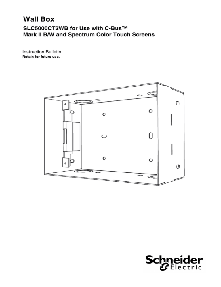
Wall Box
SLC5000CT2WB for Use with C-Bus™
Mark II B/W and Spectrum Color Touch Screens
Instruction Bulletin
Retain for future use.
Wall Box
Instruction Bulletin
63249-420-301A3
06/2011
HAZARD CATEGORIES AND SPECIAL SYMBOLS
Read these instructions carefully and look at the equipment to become
familiar with the device before trying to install, operate, service, or maintain
it. The following special messages may appear throughout this bulletin or on
the equipment to warn of potential hazards or to call attention to information
that clarifies or simplifies a procedure.
The addition of either symbol to a “Danger” or “Warning” safety label
indicates that an electrical hazard exists which will result in personal injury if
the instructions are not followed.
This is the safety alert symbol. It is used to alert you to potential personal
injury hazards. Obey all safety messages that follow this symbol to avoid
possible injury or death.
Danger indicates an immediately hazardous situation which, if not
avoided, will result in death or serious injury.
Warning indicates a potentially hazardous situation which, if not
avoided, can result in death or serious injury.
Caution indicates a potentially hazardous situation which, if not
avoided, can result in minor or moderate injury.
Caution, used without the safety alert symbol, indicates a potentially
hazardous situation which, if not avoided, can result in property
damage or improper operation.
NOTE: Provides additional information to clarify or simplify a procedure.
2
© 2010 Schneider Electric. All Rights Reserved.
63249-420-301A3
06/2011
Wall Box
Instruction Bulletin
PLEASE NOTE
Electrical equipment should be installed, operated, serviced, and maintained
only by qualified personnel. This document is not intended as an instruction
manual for untrained persons. No responsibility is assumed by Schneider
Electric for any consequences arising out of the use of this manual.
© 2010 Schneider Electric. All Rights Reserved.
3
Wall Box
Instruction Bulletin
63249-420-301A3
06/2011
INTRODUCTION
This instruction bulletin describes how to install the C-Bus™ Mark II
B/W or Spectrum Color Touch ScreenWall Box (SLC5000CT2WB).
Before You Begin
Before mounting the Wall Box, inspect the device and confirm there
are no dents or other visible damage.
The Wall Box package includes this instruction bulletin, a screw kit
(63249-420-82) for mounting the Mark II Black and White Touch
Screen, and the Wall Box. Nails, screws, and all other tools used for
installation are provided by the user.
Selecting a Location
Prior to installing the Wall Box, confirm that the mounting location
selected is in the best available position for the Mark II B/W or
Spectrum Color Touch Screen. Consider the following factors when
selecting a location:
Provide easy access to the Touch Screen while considering
obstructions such as doors.
Place the Touch Screen where infrared signals from a remote
control will not be obstructed.
Place Touch Screens where a single remote control cannot
access multiple Touch Screens simultaneously.
Leave the Touch Screen uncovered.
Place the Touch Screen where it will not be subjected to water,
humidity, direct sunlight, or heavy dust.
Only use the Touch Screen indoors.
Refer to the "Mark II B/W and Spectrum Color Touch Screen"
installation instructions for a complete list of considerations and
additional information.
4
© 2010 Schneider Electric. All Rights Reserved.
63249-420-301A3
06/2011
Wall Box
Instruction Bulletin
SAFETY PRECAUTIONS
This section contains important safety precautions that must be
followed before attempting to install or maintain electrical
equipment. Carefully read and follow the safety precautions below.
HAZARD OF ELECTRIC SHOCK, EXPLOSION, OR ARC FLASH
Apply appropriate personal protective equipment (PPE) and
follow safe electrical work practices. See NFPA 70E.
This equipment must be installed and serviced by qualified
electrical personnel.
Turn off all electrical power supplying this equipment before
working on or inside the equipment.
Always use a properly rated voltage sensing device to confirm
that power is off.
Replace all devices, doors, and covers before turning on power
to this equipment.
Failure to follow these instructions will result in death or
serious injury.
INSTALLATION
The Wall Box is designed for mounting the Mark II B/W or Spectrum
Color Touch Screen in the following conditions:
Walls are solid, such as brick or stone.
A high level of RF shielding is desired.
Wall construction is unfinished framed stud (wood or metal).
If conditions are different than listed above, or for alternative
mounting options, refer to the installation instructions provided with
the Touch Screen.
Refer to the "Wall Box Dimensions" figure and the "Wall Box
Physical Dimensions" table for Wall Box dimensions.
© 2010 Schneider Electric. All Rights Reserved.
5
Wall Box
Instruction Bulletin
63249-420-301A3
06/2011
Dimensions
Figure 1: Touch Screen Wall Box Dimensions
7.01 in.
178.05 mm
4.78 in.
121.41 mm
3.17 in.
80.51 mm
Table 1: Wall Box Dimensions
Parameter
Description
External dimensions (W x H x D)
7.01 x 4.78 x 3.17 in.
(178.05 x 121.41 x 80.51 mm)
Conduit Dimensions
Small knockout
Large knockout
0.5 in. (13 mm)
0.75 in. (19 mm)
Weight
16 oz. (453.6 g)
Mounting the Wall Box
The Wall Box is attached to a wood or metal stud frame using nails
or screws. A horizontal support beam between studs can also be
used to mount the Wall Box.
Follow the steps listed below to mount the Wall Box.
NOTE: Use the appropriate conduit adapters/connectors to
eliminate the effects of sharp edges on the Wall Box. A clamp
connector is recommended when the wiring is not being run through
conduit.
6
© 2010 Schneider Electric. All Rights Reserved.
63249-420-301A3
06/2011
Wall Box
Instruction Bulletin
1. Punch out either the large or small circular knockouts on the
Wall Box based on the conduit size selected. Refer to the "Wall
Box Dimensions" table for conduit knockout dimensions.
2. If necessary, prepare the wall by marking and cutting a hole for
the Wall Box, otherwise place the Wall Box against a stud wall
beam.
3. Attach the Wall Box into the wall or frame.
NOTE: All materials used to attach the Wall Box, such as nails
or screws, are provided by the user.
4. Feed the cables through the Wall Box. The use of conduit is
recommended. The number and positioning of cables depends
on specific installation details. Refer to the "Mark II Black and
White Touch Screen" installation instructions for cable
information.
Figure 2: Installing the Wall Box
© 2010 Schneider Electric. All Rights Reserved.
7
Wall Box
Instruction Bulletin
SUPPORT AND SERVICE
Contact the Customer Information Center for technical support by
phone at 1-888-778-2733 or e-mail at
lightingcontrol.support@us.schneider-electric.com.
Contact your local Schneider Electric service representative or
C-Bus™ system certified installer for repairs or service to your
network.
You may also find helpful information on our web site at
www.Schneider-Electric.us.
Schneider Electric, USA
320 Tech Park Drive, Suite 100
La Vergne, TN, 37086
1-888-778-2733
www.schneider-electric.us
C-Bus, Schneider Electric and SE logo are trademarks or registered
trademarks of Schneider Electric and/or its affiliates in the United States
and/or other countries.
Electrical equipment should be installed, operated, serviced, and
maintained only by qualified personnel. No responsibility is assumed by
Schneider Electric for any consequences arising out of the use of this
material.
© 2011 Schneider Electric. All Rights Reserved.
63249-420-301A3
06/2011


