VP Connector Family Data Sheet
advertisement

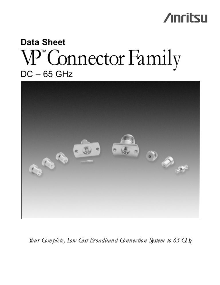
Data Sheet VP Connector Family ™ DC – 65 GHz Your Complete, Low Cost Broadband Connection System to 65 GHz VP™ Connector Family, DC to 65 GHz The new VP Connector family, with shrouds and adapters, is well suited for applications in components, systems and instrumentation to 65 GHz. Anritsu’s family of VP Connectors satisfies virtually every interface and provides an excellent and reliable performance. Features • • • • • • Superior RF Performance to 65 GHz Hermetic Connection Sliding Contact Connection to Microstrip Ground lip for handling substrates on carriers Testing capabilities using VP-VF Adapter Auto alignment capabilities on VP-VF Adapters VP Bullet The VP Bullet is a VP-VP adapter, designed to connect two modules with shrouds, back to back. The VP Bullet exhibits exceptional performance due to it’s unique design concept. The VP Bullet is designed with six slots in the outer conductor and four slots in the center conductor. The increase in the number of slots in the outer conductor reduces the insertion and extraction force to less than one half of the force required for conventional SMP connectors and thus reduces wear and tear. In the lab VP Bullets have been tested to 1000 insertions with no degradation in performance. Anritsu guarantees at least 500 connections. In addition, the VP Bullet provides a positive stop so that fingers can not be damaged during insertion. The VP Shrouds, except for the CPW versions, are designed to be used with the Anritsu V110-1 Stress Relief Contact (sliding contact). The CPW backside interface is a pin overlap design, so the center pin is directly connected to the transmission line and the substrate ground is directly attached to the ground lip. Cable Connector The VP Cable connector uses standard semi-rigid 2.16 mm cable just like the V cable Connectors. One can install standard V Cable connector on the opposite end and thus it makes the testing of the modules much easier. The VP cable connector has a flange to ensure a good rigid connection to the module. The cable connectors can also be utilized for connecting two modules back to back. VP-VF Adapters VP-VF Adapters are specifically designed for testing the modules using the Precision V Connector. The VP-VF Adapter can be replaced with a VP Bullet or VP Cable Connector. Model 01-501 Bullet Insertion and Removal Tool VP Shroud Design Anritsu VP Shrouds are based on the design concept first used in Anritsu’s Integrated V Connector®. VP Shrouds use the standard V Glass bead and the critical compensation steps required to install the glass bead in the housing are a part of the hermetic shroud design. Since Anritsu controls the critical internal dimensions, consistent performance is assured. Additionally, the ground lip allows the substrate ground to be attached directly to the connector, eliminating the long ground path common to other connector families. This short ground path improves return loss performance, especially at the high end of the frequency range. 2 01-502 VP100B Torque tool adapter VP100BCPW Solder-in CPW hermetic shroud VP100B screw-in hermetic shroud 4.15 4.94 .76 1.72 Ø3.18 2X Ø.50 Ø4.02 .57 Ø4.02 .02 3.62 3.57 ACROSS FLTS 0.24 Ø.24 Ø4.06 .38 1.53 All dimensions in mm All dimensions in mm VP100BMS10 Solder-in 10 mil Microstrip hermetic shroud VP101F VP cable adapter 2X R6.35 1.24 0.24 Ø3.18 .51 All dimensions in mm 3.62 Ø5.33 Ø3.00 10.11 Ø4.06 .58 2X Ø1.60 5.1 1.6 2X Ø.50 1.72 5.18 All dimensions in mm 5.26 1.6 10.24 6.35 VP100BMS75 Solder-in 7.5 mil Microstrip hermetic shroud VP102F VP Bullet 6.50 5.26 Ø3.05 1.72 Ø4.06 0.24 Ø1.51 3.62 .42 Ø3.18 Ø1.93 All dimensions in mm .51 All dimensions in mm 2.62 VP100BNL no lip hermetic shroud VP103F VP-VF Adapter 6.65 4.75 10.24 2X Ø1.60 THRU 3.33 1.24 Ø4.06 1.02 M7 X .75 Ø.63 10.11 Ø5.84 Ø5.33 5.1 0.24 Ø3.18 All dimensions in mm 1.6 All dimensions in mm 11.84 3 Typical High Frequency Return-Loss measured on VP102F over the range of 40 MHz to 65 GHz. Specifications: Materials: Impedance 50 Ohms Frequency DC to 65 GHz Insertion Loss 0.05 √ f (GHz) VSWR: VP102F 15 dB typical Insulation Resistance > 1200 megaohms Center conductor contact resistance 6 milliohms typical Force to engage 4.2 N typical (1 lbf typical) Force to disengage 7 N typical. (1.5 lbf typical) Center contact Retention 83 N typical. (18 lbf typical) Radial Misalignment 0.25 mm (0.010”) for VP102F Axial Misalignment 0-0.15mm (0 to 0.006”) for VP102F Hermeticity for solder-in shrouds 1 x10⁻⁸ std cc He/sec at 1 atmosphere differential Shroud Soldering 310˚C maximum for solder-in shrouds. Any heating operation to 310˚C not to exceed 10 seconds with a maximum of 3 heating operations to 310˚C. Material: Brass, gold plated over nickel per Mil-G-45204C Shrouds, VP100B, VP100BCPW, center pin: Kovar, gold plated over nickel per Mil-G-45204C VP100BMS10, VP100BMS75 Bead body: Kovar, gold plated over nickel per and VP100BNL Environmental Information: Mil-G-45204C Bead dielectric: Corning 7070 glass VP101F VP Cable adapter Beryllium-copper, gold plated over nickel per Mil-G-45204C VP102F VP Bullet Heat treated Beryllium-copper, gold plated over nickel per Mil-G-45204C Dielectric: Polyphenylene Oxide Noryl (PPO) VP103F VP-VF adapter Body: Passivated stainless steel Bead: Polyphenylene Oxide Noryl (PPO) Center conductor: Beryllium-copper, gold plated over nickel per Mil-G-45204C Tests are performed per MIL-STD-202F Operating Temperature Range –54° to +200° C for VP100BXXXX, –54°C to +125°C for VP102F, VP101F and VP103F adapter Temperature Shock 25° C to –55° C and 25° C to +200° C, method 107G, Condition B for shrouds to +125°C for bullet and cable adapter Humidity 95% at 40°C, 96 hours, Test 103B, Condition B Shock: 100 G peak sawtooth, method 213, test condition 1 Vibration Sinewave: 10 Hz to 2000 Hz, 0.06” DA, method 204, test condition D Random: 50 Hz to 2000 Hz, 11.6 Grms, Power Spectral Density 0.1 Grms2/Hz, Method 214, Test Condition I, Letter D Salt Spray 5% concentration for 48 hours, Method 101D, Condition B Voltage withstanding 500 Vac RMS, 60 seconds, method 301 Sales Centers: United States (800) ANRITSU Canada (800) ANRITSU South America 55 (21) 286-9141 ®Anritsu February, 2003; Rev: B Data subject to change without notice Microwave Measurements Division • 490 Jarvis Drive • Morgan Hill, CA 95037-2809 http://www.us.anritsu.com • FAX (408) 778-0239 Sales Centers: Europe 44 (0) 1582-433433 Japan 81 (03) 3446-1111 Asia-Pacific 65-2822400 11410-00296 VP Connector Family Data Sheet

