Uniformly accelerated motion on an
inclined track with the demonstration track
and timer 4 – 4
DAP
Introduction
An object on an inclined track is subject to constant acceleration in parallel to the track due
to the gravitational forces exerted on the object. The aim of this experiment is to confirm
the laws of motion for a uniformly accelerated motion by measuring the time that a cart
runs on the inclined demonstration track. In addition, the magnitude of the acceleration
due to gravity can be verified based on Newton's second law.
Keywords
Acceleration, frictionless motion, inclined track, distance-time law, velocity-time law,
Newton's second law, gravity, resolution of forces, acceleration due to gravity
Educational objective
If an object undergoes uniform acceleration, the distance that is covered increases in a
square manner over time in accordance with the distance-time law. In accordance with the
velocity-time law, the velocity is linear:
s (t ) = 1 ⋅ a ⋅ t 2 ,
2
v (t ) = a ⋅ t .
Depending on the angle of inclination of the track, the gravitational force acting on the cart
leads to a uniformly accelerated motion proportional to the acceleration due to gravity:
a = g ⋅ sin α .
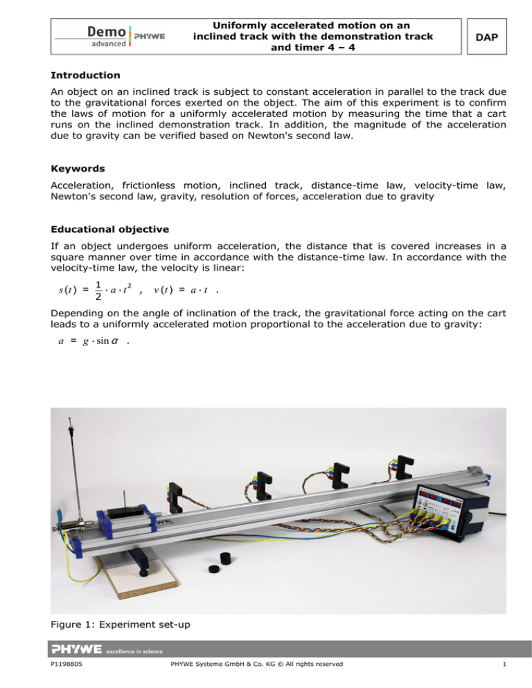
Figure 1: Experiment set-up
P1198805
PHYWE Systeme GmbH & Co. KG © All rights reserved
1
DAP
Uniformly accelerated motion on an
inclined track with the demonstration track
and timer 4 – 4
Equipment
1
1
1
1
1
1
1
4
4
1
4
5
5
1
1
1
4
2
1
1
Demonstration track, aluminium, l = 1.5 m
Cart with low-friction sapphire bearings
Shutter plate for the low-friction cart, w = 100 mm
Needle with plug
Tube with plug
Plasticine, 10 sticks
Magnet with plug for the starter system
Light barrier, compact
Holder for light barriers
Timer 4 – 4
Connecting cord, 32 A, 1000 mm, red
Connecting cord, 32 A, 1000 mm, yellow
Connecting cord, 32 A, 1000 mm, blue
Starter system for the demonstration track
End holder for the demonstration track
Weight (400 g) for the low-friction cart
Slotted weight, black, 10 g
Slotted weight, black, 50 g
Measuring tape, l = 2 m
Portable balance, OHAUS CS2000E, 2,000 g / 1 g
Option:
1 Supporting blocks, 150 mm, set of 4
11305-00
11306-00
11308-00
11202-06
11202-05
03935-03
11202-14
11207-20
11307-00
13604-99
07363-01
07363-02
07363-04
11309-00
11305-12
11306-10
02205-01
02206-01
09936-00
48911-00
02070-00
Related topics
The laws of motion for a uniformly accelerated motion can also be demonstrated by way of
experiment P1198605 "Uniformly accelerated motion with an accelerating mass". In this
case, the cart is not accelerated due to the inclination of the track, but by a mass that is
suspended from the cart by way of a piece of thread. In the experiment P1198905
"Uniformly decelerated motion", the cart is also subject to acceleration on an inclined track.
However, in this case, the acceleration acts on the cart in the opposite direction.
Tasks
1. Determination of the distance-time relationship based on several measured time values
at different distances covered by the cart.
2. Determination of the velocity-time relationship based on a measurement of the light
barrier shading times at different positions.
3. Determination of the acceleration due to gravity based on the mass of the cart and the
angle of inclination of the track.
2
PHYWE Systeme GmbH & Co. KG © All rights reserved
P1198805
Uniformly accelerated motion on an
inclined track with the demonstration track
and timer 4 – 4
DAP
Set-up
Set the experiment up as shown in Figure 1:
1. In order to compensate for slight friction effects, the track must be slightly inclined by
way of the adjusting screws at the track bases so that the cart is still just about
prevented from rolling to the right. Position an object (supporting blocks, books, a stack
of paper, etc.) under the double-footed base of the track in order to raise it by
approximately 1 to 5 cm.
2. Position the starter system at the raised left end of the track. Please note that, in order
to start the cart without an initial momentum, the starter system must be installed so
that the ram moves away from the cart when the starter system is triggered (Fig. 2).
3. Attach a plasticine-filled tube to the end holder at the right-hand end of the track in
order to stop the cart without a strong impact (Fig. 3).
4. Equip the cart with the magnet with a plug, a needle with a plug, and the shutter plate
(w = 100 mm) (see Figs. 2 and 4).
5. The mass of the cart can be varied by way of the weights.
6. Install the four light barriers on the track by way of the light barrier holders (Fig. 5).
Position the light barriers on the track so that the measuring length is divided into four
segments of roughly the same size.
7. Connect the light barriers from the left to the right to the sockets in the fields "1" to "4"
of the timer as shown in Fig. 6. In doing so, connect the yellow sockets of the light
barriers to the yellow sockets of the measuring instrument, the red sockets to their red
counterparts, and the blue sockets of the light barriers to the white sockets of the timer.
8. Connect the starter system to the two "Start" sockets of the timer. Ensure that the
polarity is correct. Connect the red socket of the starter system to the yellow socket of
the timer.
9. In order to select the triggering edge, push the two slide switches of the timer to the
right, i.e. to "falling edge" ( ).
Fig. 2: Raised starter system
without an impulse
P1198805
Fig. 3: End holder with plasticine
PHYWE Systeme GmbH & Co. KG © All rights reserved
Fig. 4: Front of the cart
3
Uniformly accelerated motion on an
inclined track with the demonstration track
and timer 4 – 4
DAP
Fig. 5: Installation of the light
barriers on the track
Fig. 6: Connection of the light
barriers and starter system
Fig. 7: Interruption of a light barrier
by the shutter plate
Procedure
1. Measure the distances s1 … s4 of the light barriers with regard to the start position of the
cart. In doing so, it must be taken into consideration that the light barriers will be
interrupted by the front edge of the shutter plate that is installed on the cart, and not
by the cart itself. The exact determination of the distances can be performed as follows:
•
Bring the cart to the start position and read the value (x0) off the measuring tape at
the right-hand side end of the cart.
•
Move the cart to a position where the right-hand side end of the shutter plate just
about interrupts the light beam of the light barrier i and then read the value (xi) off
the tape measure at the right-hand side end of the of the cart (see Fig. 7).
•
si = xi − x0 is the distance that the cart has covered from the start up to the
corresponding light barrier.
2. The cart is released by the starter system. Due to the gravity component that is applied
to the cart, it is accelerated in a constant manner.
).
3. First, measure the times t1 … t4 for covering the distances s1 … s4 in mode 2 (
) in order to determine the
Then, perform a measurement in mode 1 (
corresponding velocities. During this measurement, the shading times Δt1 … Δt4 of the
four light barriers are determined. These are then used in order to calculate the average
velocity of the cart passing through the light barriers based on the length of the shutter
plate (100 mm).
4. Record the times for up to five repetitions. Prior to every recording process, press the
"Reset" button in order to reset the display.
5. Reposition the light barriers and perform one additional series of measurements as
described hereinabove.
6. Determine the mass of the cart by way of a balance.
7. In order to determine the angle of inclination α of the track, measure the distance
between the track bases l and the height h of the object placed under the track
(compare Figure 8).
4
PHYWE Systeme GmbH & Co. KG © All rights reserved
P1198805
Uniformly accelerated motion on an
inclined track with the demonstration track
and timer 4 – 4
DAP
Observation
If the distances between the light barriers are roughly the same, it becomes clear that the
runtime differences ti and the shading time Δti become increasingly smaller along the track
due to the acceleration of the cart.
Evaluation
a) The distance-time law and the velocity-time law
1. Use five measurements of t1 … t8 and Δt1 … Δt8 to calculate the mean values t1m … t8m and
Δt1m … Δt8m.
2. The shading times are used to determine the velocities vi(tim) = w / Δtim with the shutter
plate length w = 0.1 m.
3. In the case of a uniformly accelerated motion, the acceleration a can be determined by
way of two different methods. Either by way of the distance-time law s(t) = 0.5 · a · t2
based on the runtime and the positions of the light barriers or by way of the velocity-time
law v(t) = a(t) · t based on the runtime and the corresponding velocity:
•
In order to verify the distance-time law, enter the measurement values into a (s, t2)
system of coordinates. The acceleration a can be determined graphically based on
the gradient of the straight line through the origin (0.5 · a) or by way of a calculation
(see Figure 9 and Table 1).
•
In a (v, t) system of coordinates, plot the velocities against the measured time. The
velocity-time law results graphically from the gradient of the straight line through
the origin or by calculation (see Figure 10 and Table 1).
P1198805
PHYWE Systeme GmbH & Co. KG © All rights reserved
5
DAP
Uniformly accelerated motion on an
inclined track with the demonstration track
and timer 4 – 4
Table 1: Measurement example with a cart mass mc = 800 g, l = 139 cm, h = 1.9 cm, and a
shutter plate length w = 0.100 m
s in m
tm in s
∆tm in s v in m/s a = v/tm in m/s²
(tm)² in s²
a = 2s/(tm)² in m/s²
0.20
1.724
0.394
0.254
0.147
2.97
0.135
0.50
2.740
0.263
0.380
0.139
7.51
0.133
0.80
3.474
0.214
0.468
0.135
12.07
0.133
1.10
4.075
0.184
0.542
0.133
16.61
0.132
0.05
0.817
0.661
0.151
0.185
0.67
0.150
0.35
2.282
0.308
0.325
0.142
5.21
0.134
0.65
3.132
0.234
0.427
0.136
9.81
0.132
0.95
3.788
0.196
0.509
0.134
14.35
0.132
Figure 10: Velocity-time law with
v(t) = a ⋅ t = 0.136 m/s2 ⋅ t and,
thereby, a = 0.136 m/s
b) Determination of the gravitational acceleration
The weight force Fg acting on the cart can be resolved into two parts, one component F|| in
the direction of the track and one component F perpendicular to the track. The component
causing an acceleration in the direction of the track increases with an increasing angle of
inclination α. F|| causes a uniformly accelerated motion. Figure 8 shows the vector
resolution of the force by way of a parallelogram of forces. The following applies:
F|| = Fg · sin α.
6
PHYWE Systeme GmbH & Co. KG © All rights reserved
P1198805
Uniformly accelerated motion on an
inclined track with the demonstration track
and timer 4 – 4
DAP
The angle of inclination α results from the height h of the object placed under the track and
the distance l between the two track bases: sin α = h / l. In this measurement example,
h = 1.9 cm and l =139 cm, resulting in α = 0.78°.
In accordance with Newton's second law (compare Figure 8)
F ∥ = m ⋅ g ⋅ sin α = m ⋅ a
and based on the acceleration determined in Figure 9
a = 0.133 m/s2
the following value results for the acceleration due to gravity:
gs =
a
= 9.73 m /s2 .
sin (α )
Based on the velocity measurements and Figure 10, the following value results for the
acceleration due to gravity:
g v = 9.95 m/s2 .
Note
1. Strictly speaking, the velocities vi that are calculated based on Δti, are not instantaneous
velocities, since the cart is still subject to acceleration when the shutter plate passes
through the light barrier. Consequently, the velocities result from a secant gradient and
not from a tangent gradient of the graph of s(t). With Δs = 0.1 m, a systematic error of
approximately 2% must be taken into consideration.
2. If the start position is raised further, the proportionality between acceleration and the
sine of the angle of inclination can be demonstrated. If the measurements are repeated
with different weights placed on the cart, it can be demonstrated that the acceleration
and velocity of the cart (provided that there is no friction) are not affected by the mass.
This relationship can also be demonstrated during the experiment on free fall.
P1198805
PHYWE Systeme GmbH & Co. KG © All rights reserved
7


