HCCV
Water Supply
PN 16
Hydraulically Controlled Check Valve
Full Hydraulic Transient Control
Description
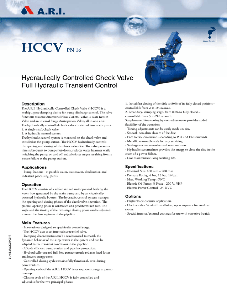
The A.R.I. Hydraulically Controlled Check Valve (HCCV) is a
multipurpose damping device for pump discharge control. The valve
functions as a one-directional Flow Control Valve, a Non-Return
Valve and an internal Surge Anticipation Valve, all in one unit.
The hydraulically controlled check valve consists of two major parts:
1. A single shaft check valve.
2. A hydraulic control system.
The hydraulic control system is mounted on the check valve and
installed at the pump station. The HCCV hydraulically controls
the opening and closing of the check valve disc. The valve prevents
slam subsequent to pump shut-down, reduces water hammer while
switching the pump on and off and alleviates surges resulting from a
power failure at the pump station.
1. Initial fast closing of the disk to 80% of its fully closed position –
controllable from 2 to 10 seconds.
2. Secondary, damping stage, from 80% to fully closed –
controllable from 5 to 200 seconds.
Supplemental fine-tuning by cam adjustments provides added
flexibility of the operation.
- Timing adjustments can be easily made on-site.
- Smooth non-slam closure of the disc.
- Face to face dimensions according to ISO and EN standards.
- Metallic removable seals for easy servicing.
- Sealing seats are corrosion and wear resistant.
- Hydraulic accumulator provides the energy to close the disc in the
event of a power failure.
- Low maintenance, long working life.
Applications
Specifications
- Pump Stations - at potable water, wastewater, desalination and
industrial processing plants.
Operation
The HCCV consists of a self-contained unit operated both by the
water flow generated by the main pump and by an electricallypowered hydraulic booster. The hydraulic control system manages
the opening and closing phases of the check valve operation. The
gradual opening phase is controlled at a predetermined rate. The
angle and the timing of the two-stage closing phase can be adjusted
to meet the flow regimen of the pipeline.
Main Features
EnC-HCCVWTR-11
- Innovatively designed to specifically control surge.
- The HCCV acts as an internal surge relief valve.
- Damping characteristics can be synchronized to match the
dynamic behavior of the surge waves in the system and can be
adapted to the transient conditions in the pipeline.
- Affords efficient pump station and pipeline protection.
- Hydraulically-opened full flow passage greatly reduces head losses
and lowers energy costs.
- Controlled closing cycle remains fully functional, even during
power failure.
- Opening cycle of the A.R.I. HCCV is set to prevent surge at pump
start-up.
- Closing cycle of the A.R.I. HCCV is fully controlled and
adjustable for the two principal phases:
- Nominal Size: 400 mm – 900 mm
- Pressure Rating: 6 bar, 10 bar, 16 bar.
- Max. Working Temp.: 70°C
- Electric Oil Pump: 3 Phase - 220 V, 5HP
- Electric Power Control: 24 DVC
Options
- Higher back-pressure application.
- Horizontal or Vertical Installation, upon request - for confined
spaces.
- Special internal/external coatings for use with corrosive liquids.
HCCV
Typical Power Failure Closing
Characteristics
The first fast closing angle (%) and time (t1) are continuously
adjustable depending on the hydraulic characteristicsof the line.The
second damping closure is adjusted to include the surge wave return
time: 2L/c.This allows a part of the surge wave to be absorbed by the
HCCV and pump resistance.
Example of three closing regimes
HCCV
NR-040 HC PARTS LIST AND
SPECIFICATION
No.
Part
Material
1.
Body
Ductile Iron
2.
Shaft
St. St. 17-4 PH
3.
Hydraulic Piston
4.
Accumulator
5.
Logic Block
6.
Oil Tank
7.
Electric Motor
8.
Operator Arm
9.
Limit Switch
10.
Hydraulic Valve
11.
Mechanical Interface
ASTM A536 60-40-18
Steel
Steel
Ductile Iron
ASTM A536 60-40-18
NR-050 HC PARTS LIST AND SPECIFICATION
No.
Part
Material
1.
Body
2.
Shaft
Hydraulic Piston
Accumulator
Logic Block
Oil Tank
Electric Motor
Mechanical Interface
Ductile Iron A
STM A536 60-40-18
St. St. SAE 431
3.
4.
5.
6.
7.
8.
9.
10.
11.
12.
13.
Limit Switch
Hydraulic Valve
Counterweights
Operator Arm
Control Box
Steel
Ductile Iron
ASTM A536 60-40-18
Steel
Steel
1
12
2
11
HCCV
A.R.I. FLOW CONTROL ACCESSORIES Ltd. www.arivalves.com ari@ari.co.il Tel: 972-4-6761988
A.R.I. FLOW CONTROL ACCESSORIES Ltd. reserves the right to make product changes without prior notice. To insure receiving updated information on parts specifications, please call the export dept. at the A.R.I.
factory. A.R.I. FLOW CONTROL ACCESSORIES Ltd. shall not be held liable for any errors. All rights reserved.


