Experiment 7: PID Motor Speed Control
Introduction
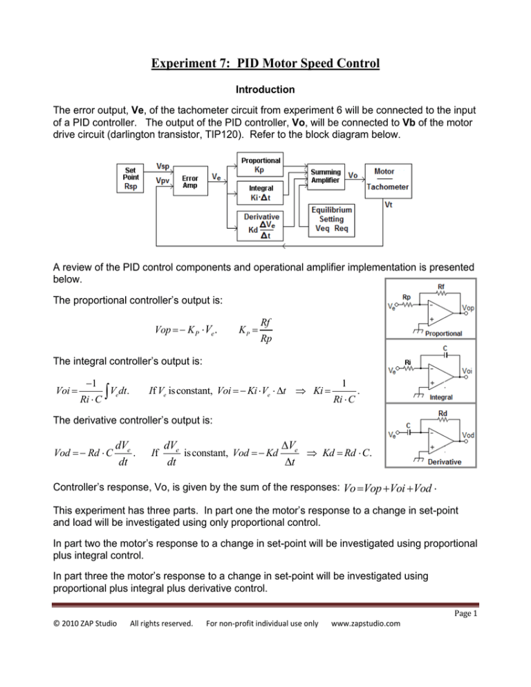
The error output, Ve, of the tachometer circuit from experiment 6 will be connected to the input
of a PID controller. The output of the PID controller, Vo, will be connected to Vb of the motor
drive circuit (darlington transistor, TIP120). Refer to the block diagram below.
A review of the PID control components and operational amplifier implementation is presented
below.
The proportional controller’s output is:
Vop K P Ve .
KP
Rf
Rp
The integral controller’s output is:
Voi
1
V dt.
Ri C
If Ve is constant, Voi Ki Ve t Ki
e
1
Ri C
.
The derivative controller’s output is:
Vod Rd C
dVe
.
dt
If
dVe
Ve
is constant, Vod Kd
Kd Rd C.
dt
t
Controller’s response, Vo, is given by the sum of the responses: Vo Vop Voi Vod
This experiment has three parts. In part one the motor’s response to a change in set-point
and load will be investigated using only proportional control.
In part two the motor’s response to a change in set-point will be investigated using proportional
plus integral control.
In part three the motor’s response to a change in set-point will be investigated using
proportional plus integral plus derivative control.
Page 1
© 2010 ZAP Studio
All rights reserved.
For non-profit individual use only
www.zapstudio.com
Parts and Equipment Required
Oscilloscope / Data Logger, DMM, Power Supply: 0 to 6V, 2 amps; +/- 9 volts.
ICs: LM35, two LM358, Transistor: TIP120 or equiv.
Resistors: Five 100k, 220, 820, 91k, ¼W, 5%.
Potentiometers: 10k, one turn trim pot. Capacitors: two 10µF, 10nF, 470nF.
Motor-generator-tachometer set.
Procedure Part 1: Proportional Control
1.
Study the PID control system schematic diagram below. The motor-tachometer-error
amplifier circuit of experiment 6 is connected to the proportional, integral, derivative,
and summer op-amp circuits as shown. U3A is a proportional amplifier. U4A is an
integrator, and U4B is a differentiator. U3B sums the proportional, integral, and
derivative components and the equilibrium voltage.
Procedure
2.
Build and connect the PID controller circuit as shown in the diagram above, but do not
turn on the power supplies.
3.
Connect Vin to ground (not to Ve). Connect oscilloscope channel 1 to Vsp and
channel 2 to Vpv. Set both channels to DC input, 0.5 volt per division.
Set the zero reference for both channels to the bottom of the screen so that you can
measure zero to four volts with both channels.
Set the time base to 100µSec per division and the trigger to AUTO and external input.
Page 2
© 2010 ZAP Studio
All rights reserved.
For non-profit individual use only
www.zapstudio.com
4.
Turn on the power supplies. Motor speed jumper, Jsp, should be connected.
Measure the set point voltage, Vsp, (ch. 1) and the set point motor speed in rpm.
Vsp: ____________________
RPM: ____________________
5.
Adjust equilibrium (offset) potentiometer, Req, so that Vpv (on channel 2 of the
oscilloscope) is equal to Vsp.
6.
Disconnect Vin from ground. Connect Vin to Ve. This enables the proportional control
mode. Check that the motor speed, Vpv, remains at the set point speed. The motor is
now running under proportional control with a proportional gain of about 2.
7.
Set time base to 1 second per division. Set trigger mode to “auto” and the trigger
point to the left edge of the screen. Each scan will be for a duration of 10 seconds.
8.
The objective of the following procedure is to capture the motor speed response to a
change in set point, Vs, and to a change in load. The set point will be changed by
pulling out the jumper, Jsp.
Use waveform capture software, such as “Tek OpenChoice”, to capture the motor’s
response. The lab instructor may have additional information.
a)
Begin with the motor running at the equilibrium speed (about 2800 rpm – Jsp is
connected). Start the acquisition when the trace is on the left side of the screen.
b)
After about 4 seconds (4 horizontal divisions) change the set point by pulling out
jumper, Jsp. Stop the capture when the trace reaches the right side of the screen.
c)
Save the result to a word processor file named Exp 7. Label the response type as
“Kp = 2, set point change”.
d)
Repeat step (a). After about 4 seconds (4 horizontal divisions) connect a 47 ohm
load resistor to the generator. The resistor should be able to be connected to the
generator by inserting one wire into the protoboard. Stop the capture when the
trace reaches the right side of the screen. Remove the 47 ohm resistor.
e)
Save the result to the word processor file named Exp 7. Label the response type
as “Kp = 2, load change”.
f)
Replace Rp with a 4.7k resistor to change the proportional gain to 10. Repeat
steps (a) and (b).
g)
Save the result to the word processor file named Exp 7. Label the response type
as “Kp = 10, set point change”.
h)
Repeat step (a). After about 4 seconds (4 horizontal divisions) connect a 47 ohm
load resistor to the generator. Stop the capture when the trace reaches the right
side of the screen. Remove the 47 ohm resistor.
Page 3
© 2010 ZAP Studio
All rights reserved.
For non-profit individual use only
www.zapstudio.com
i)
Save the result to the word processor file named Exp 7. Label the response type
as “Kp = 10, load change”. Reconnect Jsp.
Procedure Part 2: Proportional + Integral Control
1.
Change the proportional gain back to 2 by replacing Rp with a 47k ohm resistor.
Check that the motor is running at the equilibrium speed (about 2800 rpm).
2.
Connect circuit node Ti to circuit node Ts. This adds an integral gain of about 4.5.
a) Begin with the motor running at the equilibrium speed (about 2800 rpm – Jsp is
connected). Start the acquisition when the trace is on the left side of the screen.
b) After 4 seconds (4 horizontal divisions) change set point by pulling out jumper,
Jsp. Stop the capture when the trace reaches the right side of the screen.
c) Save result to the file named Exp 7. Label the response type as “Kp = 2, Ki = 4.5,
set point change”.
d) Change the integral gain to 9.7 by replacing Ri with a 220k ohm resistor.
Repeat steps (a) and (b). Save the result to the word processor file named Exp 7.
Label the response type as “Kp = 2, Ki = 9.7 set point change”.
Procedure Part 3: Proportional + Integral + Derivative Control
1.
Check that the motor is running at the equilibrium speed (about 2800 rpm).
2.
Connect circuit node Td to circuit node Ts. This adds a derivative gain of about 0.1.
a) Begin with the motor running at the equilibrium speed (about 2800 rpm – Jsp is
connected). Start the acquisition when the trace is on the left side of the screen.
b) After 4 seconds (4 horizontal divisions) change set point by pulling out jumper,
Jsp. Stop the capture when the trace reaches the right side of the screen.
c) Save result to the file named Exp 7. Label the response type as “Kp = 2, Ki = 4.5,
Kd = 0.1”.
d) Increase the derivative gain by replacing the 100nF capacitor with a 470nF.
e) Repeat steps (a) through (c).
3.
Optional: Based on the results of all three parts of this experiment, vary the
proportional, integral, and derivative gains to optimize the motor’s response to a
change of set point.
Page 4
© 2010 ZAP Studio
All rights reserved.
For non-profit individual use only
www.zapstudio.com
Analysis
Write an analysis for each screen capture that includes:
1.
Steady state error.
2.
Rise and fall times.
3.
Over-shoot and under-shoot.
4.
Settling time.
5.
Oscillation frequency if under damped.
6.
Optional part, part 3 step 3: present the results of optimizing the motor’s response.
Write a summary or conclusion at the end of the report. Divide the report into three sections:
proportional only, proportional plus integral, and proportional plus integral plus derivative.
Divide the proportional section into set point change results and load change results.
Each group may collaborate on the report and turn it in as a group project.
Page 5
© 2010 ZAP Studio
All rights reserved.
For non-profit individual use only
www.zapstudio.com


