Ohm`s Law - Las Positas College
advertisement

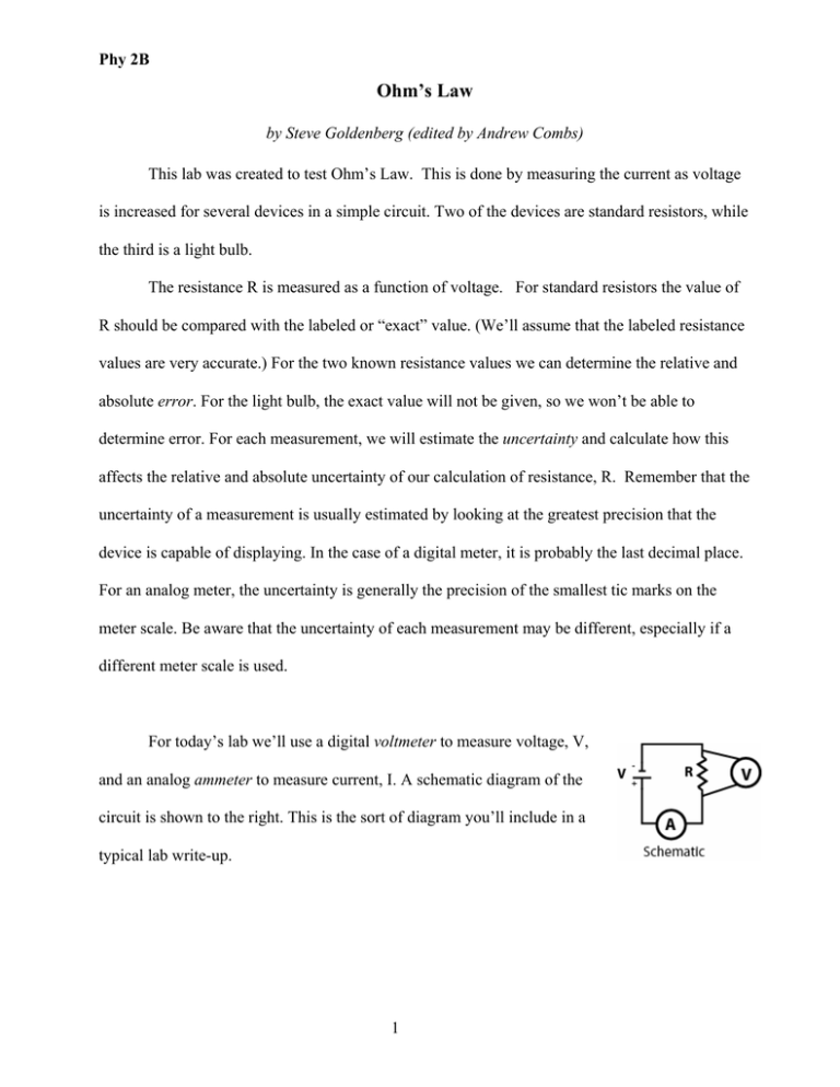
Phy 2B Ohm’s Law by Steve Goldenberg (edited by Andrew Combs) This lab was created to test Ohm’s Law. This is done by measuring the current as voltage is increased for several devices in a simple circuit. Two of the devices are standard resistors, while the third is a light bulb. The resistance R is measured as a function of voltage. For standard resistors the value of R should be compared with the labeled or “exact” value. (We’ll assume that the labeled resistance values are very accurate.) For the two known resistance values we can determine the relative and absolute error. For the light bulb, the exact value will not be given, so we won’t be able to determine error. For each measurement, we will estimate the uncertainty and calculate how this affects the relative and absolute uncertainty of our calculation of resistance, R. Remember that the uncertainty of a measurement is usually estimated by looking at the greatest precision that the device is capable of displaying. In the case of a digital meter, it is probably the last decimal place. For an analog meter, the uncertainty is generally the precision of the smallest tic marks on the meter scale. Be aware that the uncertainty of each measurement may be different, especially if a different meter scale is used. For today’s lab we’ll use a digital voltmeter to measure voltage, V, and an analog ammeter to measure current, I. A schematic diagram of the circuit is shown to the right. This is the sort of diagram you’ll include in a typical lab write-up. 1 Phy 2B To help you set up the circuit properly, an additional, slightly more lifelike figure is shown as well (see figure to the right). The lab is described here as a series of numbered steps. In your lab write-up, you’ll describe the procedure and results in your own words in paragraph form—not a numbered list as shown here. What to do: 1) Part A: Set up the circuit as shown in the figure above, starting with a 10 Ω resistor. Vary the voltage from 0.0 volts to 12.0 volts in 0.5 volt increments by adjusting the DC power supply, measuring voltage with the digital voltmeter. With the ammeter, measure I for each voltage. Fill out a table like the one below, being sure to record the uncertainties of each voltage and current measurement. Include your calculated values for R, relative and absolute V I ∆V (V) (A) (V) 0.0 0.5 1.0 1.5 … 12.0 ∆I (A) Meas. R=V/I Exact R (Ω) 10 10 10 10 … 10 Rel. Uncert ∆R/R Abs. Uncert ∆R (Ω) Abs. Error R (Ω) Rel. Error R uncertainty, and absolute and relative error. The ∆V and ∆I are obtained from the precision limits of the voltmeter and ammeter, respectively (e.g., the number of digits beyond the decimal point). Include your table in the Data/Results section of the lab. Note, 2 Phy 2B the absolute and relative errors are calculated from Rexact – Rmeasured , while the absolute and relative uncertainties can be calculated using ∆R = Rmax − Rmin = V + ∆V V − ∆ V − I − ∆I I + ∆I where Rmax and Rmin are upper and lower bounds on the measure of R, respectively. It is probably best to put all the data in Excel and program all the error calculations. 2) Plot I vs. V using either graph paper or a computer program, such as EXCEL. If you use EXCEL, you can either measure the slope of the graph from your plot or use the statistical tools of EXCEL (see the help section) to have it calculate the best slope for your plotted points. Remember that the resistance at any voltage is the reciprocal of the slope at that point. (R = 1/slope). Do the plotted points on the I vs. V graph lie in a straight line or a curved line? What is the significance of its shape? Be sure to discuss this and your other results in one or two paragraphs in the Data/Analysis section of your lab. In the Data/Analysis section also show one sample calculation for each different type of calculation, and briefly, but specifically outline what you consider to be the sources of error. Please don’t show me all of your calculations—that’s what calculators and computers are for! 3) Part B: Repeat steps 1 and 2 above, but using a 50 Ω resistor. 4) Part C: Repeat steps 1 and 2, but use the light bulb instead of a resistor. Your table for part C will not show relative and absolute error, since you haven’t been given the “exact” values. 3


