LED COMMERCIAL DOWNLIGHTS
INSTALLATION INSTRUCTIONS
S-DL4-A / S-DL4T-A , S-DL6-A / S-DL6T-A , S-DL8-A / S-DL8T-A
IMPORTANT SAFEGUARDS
When using electrical equipment, basic safety precautions should always be followed including the following:
READ AND FOLLOW ALL SAFETY INSTRUCTIONS
1.
2.
To avoid the possibility of electrical shock, turn off power supply before installation or servicing.
Product must be installed in accordance with NEC or your local electrical code. lf you are not familiar with these codes
and requirements, consult a qualified electrician.
3.
This fixture must be supported by main runners or other building structure that is capable of supporting fixture weight.
4.
These fixtures are thermally protected. Do not install insulation within 3 inches (76 mm) of fixture sides or junction
box nor above fixture in such a manner as to entrap heat.
5.
Blinking lamp may indicate fixture is too close to insulation.
SAVE THESE INSTRUCTIONS FOR FUTURE REFERENCE
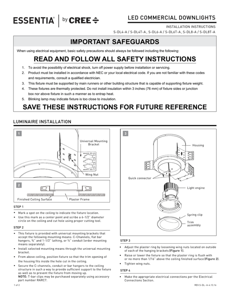
LUMINAIRE INSTALLATION
1
3
Universal Mounting
Bracket
Housing
Wing Nut
Quick connector
2
Finished Ceiling Surface
Light engine
Plaster Frame
STEP 1
•
Mark a spot on the ceiling to indicate the fixture location.
• Use this mark as a center point and scribe a 6-1/2” diameter
circle on the ceiling and cut hole using proper cutting tool.
Spring clip
Trim
assembly
STEP 2
• This fixture is provided with universal mounting brackets that
accept the following mounting means: C-Channels, flat bar
hangers, ¾” and 1-1/2” lathing, or ½” conduit (order mounting
means separately).
• Install selected mounting means through the universal mounting
bracket.
• From above ceiling, position fixture so that the trim opening of
the housing fits inside the hole cut in the ceiling.
• Secure the C-channels, conduit or bar hangers to the ceiling
structure in such a way to provide sufficient support to the fixture
as well as to prevent the fixture from moving up.
NOTE: T-bar clips may be purchased separately using accessory
part number RARC7.
1 of 2
STEP 3
•
Adjust the plaster ring by loosening wing nuts located on outside
of each of the hanging brackets (Figure 1).
•
Raise or lower the fixture so that the plaster ring is flush with
or no more than 1/16” above the ceiling finished surface (Figure 2).
•
Tighten wing nuts.
STEP 4
•
Make the appropriate electrical connections per the Electrical
Connections Section.
REV.S-DL- A-4.13.16
ELECTRICAL CONNECTIONS
STEP 1
SUPPLY WIRING
4
•
LUMINAIRE
JUNCTION
BOX
LINE-BLACK
•
•
•
LINE
NEUTRAL
GREEN
a. Connect the black fixture lead to the voltage supply lead.
b. Connect the white fixture lead to the neutral supply lead.
c. Connect the green or green/yellow ground lead to the supply
ground lead.
d. If dimming with 0-10V, connect the violet and gray dimming
wires to the corresponding wires on the dimmer. Incoming
dimming leads from the 0-10V dimmer must be Class 1 wire.
e. If not using with 0-10V dimming, cap off violet and gray
dimming leads with separate wire nuts.
NEUTRAL-WHITE
GROUND-GREEN
+DIM-VIOLET
•
•
0-10V
DIMMER
Using customer supplied 90°C minimum rated wire connectors,
make the following electrical connections within the junction
box (Figure 4) :
-DIM-GRAY
TRIM INSTALLATION
5
7
Yoke
assembly
Quick
connector
Spring clip
Trim
assembly
6
STEP 1
Mounting
bracket
Light Engine
•
Plug the connector of the light engine onto the connector of
the housing (Figure 5).
STEP 2
•
Carefully push the light engine into the housing (Figure 6).
•
Tighten mounting screw to secure the frame to the bottom
flange of the light engine (Figure 6).
STEP 3
•
Rotate and tilt yoke assembly to desired aiming position
(Figure 7).
STEP 4
•
Mounting
screw
Squeeze the spring clips on the trim assembly together as shown
and install it into the light engine assembly (Figure 7).
Trim flange
© 2016 Cree, Inc. All rights reserved. For informational purposes only. Content is subject to change.
See lighting.cree.com/warranty for warranty and specifications. Cree® and Essentia® are registered
trademarks of Cree, Inc.
US: lighting.cree.com
T (800) 236-6800 F (262) 504-5415
Canada: www.cree.com/canada
T (800) 473-1234 F(800) 890-7507
2 of 2
REV.S-DL-A-4.13.16

