Honeywell
HVBGPIO
DIP SWITCHES/JUMPERS SETTINGS & CONNECTION INSTRUCTION
This instruction gives general information of DIP Switch settings, Jumper settings, and Rear Panel connection of HVBGPIO product. For
more details, please refer to Document 800-02530 “HVBGPIO User Guide”.
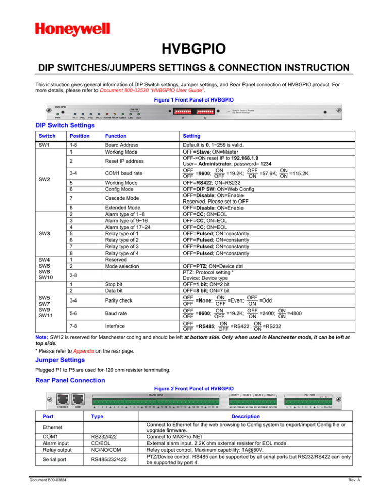
Figure 1 Front Panel of HVBGPIO
DIP Switch Settings
Switch
Position
Function
Setting
SW1
1-8
1
Board Address
Working Mode
2
Reset IP address
Default is 0, 1~255 is valid.
OFF=Slave; ON=Master
OFF->ON reset IP to 192.168.1.9
User= Administrator; password= 1234
OFF
ON
OFF
ON
=9600;
=19.2K;
=57.6K;
=115.2K
OFF
OFF
ON
ON
OFF=RS422; ON=RS232
OFF=DIP SW; ON=Web Config
OFF=Disable; ON=Enable
Reserved, Please set to OFF
OFF=Disable; ON=Enable
OFF=CC; ON=EOL
OFF=CC; ON=EOL
OFF=CC; ON=EOL
OFF=Pulsed; ON=constantly
OFF=Pulsed; ON=constantly
OFF=Pulsed; ON=constantly
OFF=Pulsed; ON=constantly
SW2
SW3
SW4
SW6
SW8
SW10
SW5
SW7
SW9
SW11
3-4
COM1 baud rate
5
6
Working Mode
Config Mode
7
Cascade Mode
8
2
3
4
5
6
7
8
1
2
Extended Mode
Alarm type of 1~8
Alarm type of 9~16
Alarm type of 17~24
Relay type of 1
Relay type of 2
Relay type of 3
Relay type of 4
Reserved
Mode selection
OFF=PTZ; ON=Device ctrl
PTZ: Protocol setting *
Device: Device type
OFF=1 bit; ON=2 bit
OFF=8 bit; ON=7 bit
OFF
ON
OFF
=None;
=Even;
=Odd
OFF
OFF
ON
OFF
ON
OFF
ON
=9600;
=19.2K;
=2400;
=4800
OFF
OFF
ON
ON
OFF
ON
ON
=RS485;
=RS422;
=RS232
OFF
OFF
ON
3-8
1
2
Stop bit
Data bit
3-4
Parity check
5-6
Baud rate
7-8
Interface
Note: SW12 is reserved for Manchester coding and should be left at bottom side. Only when used in Manchester mode, it can be left at
top side.
* Please refer to Appendix on the rear page.
Jumper Settings
Plugged P1 to P5 are used for 120 ohm resister terminating.
Rear Panel Connection
Figure 2 Front Panel of HVBGPIO
Port
Type
Ethernet
COM1
Alarm input
Relay output
RS232/422
CC/EOL
NC/NO/COM
Serial port
RS485/232/422
Document 800-03824
Description
Connect to Ethernet for the web browsing to Config system to export/import Config flie or
upgrade firmware.
Connect to MAXPro-NET.
External alarm input. 2.2K ohm external resister for EOL mode.
Relay output control. Maximum capability: 1A@50V.
PTZ/Device control. RS485 can be supported by all serial ports but RS232/RS422 can only
be supported by port 4.
Rev. A
HVBGPIO DIP SWITCHES/JUMPERS and CONNECTION INSTRUCTION
Honeywell
Appendix
PTZ Protocol Setting
Protocol
Pelco D
Pelco P
Diamond
JVC(Reserved)
VCL
Panasonic
AD
IntelliBus
User-Define
B8
OFF
OFF
OFF
OFF
OFF
OFF
OFF
OFF
OFF
B7
OFF
OFF
OFF
OFF
OFF
OFF
OFF
OFF
OFF
B6
OFF
OFF
OFF
OFF
OFF
OFF
OFF
OFF
ON
B5
OFF
OFF
OFF
OFF
ON
ON
ON
ON
OFF
B4
OFF
OFF
ON
ON
OFF
OFF
ON
ON
OFF
B3
OFF
ON
OFF
ON
OFF
ON
OFF
ON
OFF
Honeywell
http://www.security.honeywell.com/
+1.800.796.CCTV (North America only)
© 2009 Honeywell International Inc. All rights reserved. No part of this publication may be reproduced by any means without written permission from Honeywell
Video Systems. The information in this publication is believed to be accurate in all respects. However, Honeywell Video Systems cannot assume responsibility for
any consequences resulting from the use thereof. The information contained herein is subject to change without notice. Revisions or new editions to this
publication may be issued to incorporate such changes.
Document 800-03824
Rev. A


