UL Design U411
advertisement
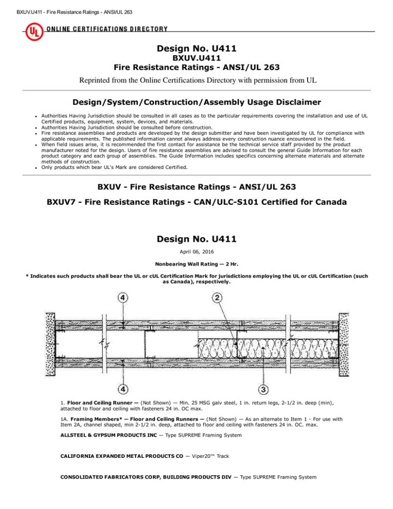
BXUV.U411 ­ Fire Resistance Ratings ­ ANSI/UL 263 Design No. U411 BXUV.U411 Fire Resistance Ratings ­ ANSI/UL 263 Reprinted from the Online Certifications Directory with permission from UL Design/System/Construction/Assembly Usage Disclaimer Authorities Having Jurisdiction should be consulted in all cases as to the particular requirements covering the installation and use of UL Certified products, equipment, system, devices, and materials. Authorities Having Jurisdiction should be consulted before construction. Fire resistance assemblies and products are developed by the design submitter and have been investigated by UL for compliance with applicable requirements. The published information cannot always address every construction nuance encountered in the field. When field issues arise, it is recommended the first contact for assistance be the technical service staff provided by the product manufacturer noted for the design. Users of fire resistance assemblies are advised to consult the general Guide Information for each product category and each group of assemblies. The Guide Information includes specifics concerning alternate materials and alternate methods of construction. Only products which bear UL's Mark are considered Certified. BXUV ­ Fire Resistance Ratings ­ ANSI/UL 263 BXUV7 ­ Fire Resistance Ratings ­ CAN/ULC­S101 Certified for Canada Design No. U411 April 06, 2016 Nonbearing Wall Rating — 2 Hr. * Indicates such products shall bear the UL or cUL Certification Mark for jurisdictions employing the UL or cUL Certification (such as Canada), respectively. 1. Floor and Ceiling Runner — (Not Shown) — Min. 25 MSG galv steel, 1 in. return legs, 2­1/2 in. deep (min), attached to floor and ceiling with fasteners 24 in. OC max. 1A. Framing Members* — Floor and Ceiling Runners — (Not Shown) — As an alternate to Item 1 ­ For use with Item 2A, channel shaped, min 2­1/2 in. deep, attached to floor and ceiling with fasteners 24 in. OC. max. ALLSTEEL & GYPSUM PRODUCTS INC — Type SUPREME Framing System CALIFORNIA EXPANDED METAL PRODUCTS CO — Viper20™ Track CONSOLIDATED FABRICATORS CORP, BUILDING PRODUCTS DIV — Type SUPREME Framing System 1/9 BXUV.U411 ­ Fire Resistance Ratings ­ ANSI/UL 263 MARINO/WARE, DIV OF WARE INDUSTRIES INC — Viper20™ Track QUAIL RUN BUILDING MATERIALS INC — Type SUPREME Framing System SCAFCO STEEL STUD MANUFACTURING CO — Type SUPREME Framing System STEEL CONSTRUCTION SYSTEMS INC — Type SUPREME Framing System UNITED METAL PRODUCTS INC — Type SUPREME Framing System 1B. Floor and Ceiling Runners — (Not Shown) — For use with Item 2B­ Channel shaped, fabricated from min 20 MSG corrosion­protected or galv steel, min width to accommodate stud size, with min 1 in. long legs, attached to floor and ceiling with fasteners spaced max 24 in. OC. 1C. Framing Members* — Floor and Ceiling Runners — (Not Shown) — As an alternate to Item 1 ­ For use with Item 2C, channel shaped, min 2­1/2 in. wide fabricated from min 0.015 in. thick galv steel, attached to floor and ceiling with fasteners 24 in. OC. max. CLARKDIETRICH BUILDING SYSTEMS — CD ProTRAK DMFCWBS L L C — ProTRAK MBA METAL FRAMING — ProTRAK RAM SALES L L C — Ram ProTRAK STEEL STRUCTURAL PRODUCTS L L C — Tri­S ProTRAK 1D. Framing Members* — Floor and Ceiling Runners — (Not Shown) — As an alternate to Item 1 ­ For use with Item 2D, channel shaped, min 2­1/2 in. wide fabricated from min 0.018 in. thick galv steel, attached to floor and ceiling with fasteners 24 in. OC. max. TELLING INDUSTRIES L L C — TRUE­TRACK™ 1E. Framing Members* — Floor and Ceiling Runners — (Not Shown) — As an alternate to Item 1 ­ For use with Item 2E, channel shaped, min 2­1/2 in. wide fabricated from min 25 MSG steel, attached to floor and ceiling with fasteners 24 in. OC. max. KIRII (HONG KONG) LTD — Type KIRII 1F. Floor and Ceiling Runners — (Not Shown) — Channel shaped, fabricated from min 0.02 in. galv steel, min width to accommodate stud size, with min 1 in. long legs, for use with studs specified below and fabricated from min 0.02 in. galv steel or thicker, attached to floor and ceiling with fasteners spaced max 24 in. OC. MARINO/WARE, DIV OF WARE INDUSTRIES INC — Viper20™ Track VT100. 1G. Framing Members* — Floor and Ceiling Runners — (Not Shown) — As an alternate to Item 1 ­ For use with Item 2G, channel shaped, min 2­1/2 in. deep, attached to floor and ceiling with fasteners 24 in. OC. max. TELLING INDUSTRIES L L C — Viper20™ Track 1H. Framing Members* — Floor and Ceiling Runners — (Not Shown) — As an alternate to Item 1 ­ For use with Item 2J. Channel shaped, attached to floor and ceiling with fasteners 24 in. OC. max. BAILEY METAL PRODUCTS LTD — Type PLATINUM PLUS 2/9 BXUV.U411 ­ Fire Resistance Ratings ­ ANSI/UL 263 2. Steel Studs — Min 2­1/2 in. deep, formed of min 25 MSG galv steel max stud spacing 24 in. OC. Studs to be cut 3/4 in. less than assembly height. 2A. Framing Members* — Steel Studs — As an alternate to Item 2 ­ For use with Item 1G, channel shaped studs, min 2­1/2 in. deep, spaced a max of 24 in. OC. Studs to be cut 3/4 in. less than assembly height. ALLSTEEL & GYPSUM PRODUCTS INC — Type SUPREME Framing System CALIFORNIA EXPANDED METAL PRODUCTS CO — Viper20™ CONSOLIDATED FABRICATORS CORP, BUILDING PRODUCTS DIV — Type SUPREME Framing System MARINO/WARE, DIV OF WARE INDUSTRIES INC — Viper20™ QUAIL RUN BUILDING MATERIALS INC — Type SUPREME Framing System SCAFCO STEEL STUD MANUFACTURING CO — Type SUPREME Framing System STEEL CONSTRUCTION SYSTEMS INC — Type SUPREME Framing System UNITED METAL PRODUCTS INC — Type SUPREME Framing System 2B. Steel Studs — (As an alternate to Item 2, For use with Item 4D) Channel shaped, fabricated from min 20 MSG corrosion­protected or galv steel, 3­1/2 in. min depth, spaced a max of 16 in. OC. Studs friction­fit into floor and ceiling runners. Studs to be cut 5/8 to 3/4 in. less than assembly height. 2C. Framing Members* — Steel Studs — As an alternate to Item 2 ­ For use with Item 1C, channel shaped studs, min 2­1/2 in. wide fabricated from min 0.015 in. thick galv steel, spaced a max of 24 in. OC. Studs to be cut 3/4 in. less than assembly height. CLARKDIETRICH BUILDING SYSTEMS — CD ProSTUD DMFCWBS L L C — ProSTUD MBA METAL FRAMING — ProSTUD RAM SALES L L C — Ram ProSTUD STEEL STRUCTURAL PRODUCTS L L C — Tri­S ProSTUD 2D. Framing Members* — Steel Studs — As an alternate to Item 2 ­ For use with Item 1D, channel shaped studs, min 2­1/2 in. wide fabricated from min 0.018 in. thick galv steel, spaced a max of 24 in. OC. Studs to be cut 3/4 in. less than assembly height. TELLING INDUSTRIES L L C — TRUE­STUD™ 2E. Framing Members* — Steel Studs — As an alternate to Item 2 — For use with Item 1E, channel shaped studs, min 2­1/2 in. wide fabricated from min 25 MSG steel, spaced a max of 24 in. OC. Studs to be cut 3/4 in. less than assembly height. KIRII (HONG KONG) LTD — Type KIRII 2F. Framing Members* — Steel Studs — As an alternate to Item 2 ­ For use with Item 1G, channel shaped studs, min 2­1/2 in. deep, spaced a max of 24 in. OC. Studs to be cut 3/4 in. less than assembly height. TELLING INDUSTRIES L L C — Viper20™ 3/9 BXUV.U411 ­ Fire Resistance Ratings ­ ANSI/UL 263 2G. Framing Members* — Steel Studs — As an alternate to Item 2 — For use with Item 1, channel shaped studs, Min 2­1/2 in. deep, formed of min 25 MSG galv steel max stud spacing 24 in. OC. Studs to be cut 3/4 in. less than assembly height. EB MéTAL INC — EB Stud 2H. Framing Members* — Steel Studs — As an alternate to Item 2 — For use with Item 1, channel shaped studs, Min 2­1/2 in. deep, formed of min 25 MSG galv steel max stud spacing 24 in. OC. Studs to be cut 3/4 in. less than assembly height. OLMAR SUPPLY INC — PRIMESTUD 2I. Framing Members* — Steel Studs — As an alternate to Item 2 ­ For use with Item 1A (3­5/8 in. wide track), channel shaped studs, fabricated from min 25 MSG corrosion­protected steel, 1­1/4 in. wide by 3­5/8 in. deep, spaced a max of 24 in. OC. Studs to be cut 3/8 to 3/4 in. less than assembly height. MARINO/WARE, DIV OF WARE INDUSTRIES INC — StudRite™ 2J. Framing Members* — Steel Studs — As an alternate to Item 2 ­ For use with Item 1H, channel shaped, min 3­ 5/8 in. wide, spaced a max of 24 in. OC. Studs to be cut 3/8 to 3/4 in. less than assembly height. BAILEY METAL PRODUCTS LTD — Type PLATINUM PLUS 3. Batts and Blankets* — (Optional) — Mineral wool or glass fiber batts partially or completely filling stud cavity. See Batts and Blankets (BZJZ) category for names of manufacturers. 3A. Fiber, Sprayed* — As an alternate to Batts and Blankets (Item 3) — (100% Borate Formulation) — Spray applied cellulose material. The fiber is applied with water to completely fill the enclosed cavity in accordance with the application instructions supplied with the product with a nominal dry density of 2.7 lb/ft3. Alternate Application Method: The fiber is applied without water or adhesive at a nominal dry density of 3.5 lb/ft3, in accordance with the application instructions supplied with the product. U S GREENFIBER L L C — INS735 & INS745 for use with wet or dry application. INS765LD and INS770LD are to be used for dry application only. 3B. Fiber, Sprayed* — As an alternate to Batts and Blankets (Item 3) and Item 3A ­ Spray applied cellulose insulation material. The fiber is applied with water to interior surfaces in accordance with the application instructions supplied with the product. Applied to completely fill the enclosed cavity. Minimum dry density of 4.3 pounds per cubic ft. NU­WOOL CO INC — Cellulose Insulation 3C. Fiber, Sprayed* — As an alternate to Batts and Blankets (Item 3) — Spray applied cellulose fiber. The fiber is applied with water to completely fill the enclosed cavity in accordance with the application instructions supplied with the product. The minimum dry density shall be 4.30 lbs/ft3. INTERNATIONAL CELLULOSE CORP — Celbar­RL 4. Gypsum Board* — 5/8 in. thick, outer layer paper, glass mat or vinyl surfaced. (Laminated System) Gypsum board applied vertically in two layers. Inner layer attached to studs with 1 in. long Type S steel screws spaced 8 in. OC along vertical edges, and 12 in. OC in the field and outer layer laminated to inner layer with joint compound, applied with a notched spreader producing continuous beads of compound about 3/8 in. in diameter, spaced not greater than 2 in. OC. Joints of laminated outer layer offset 12 in. from inner layer joints Outer layer gypsum board attached to floor and ceiling runner track with 1­5/8 in. long Type S steel screws spaced 12 in. OC. Optional, (Direct Attached System), Inner layer attached to studs with 1 in. long Type S steel screws spaced 16 in. OC in the field and along the vertical edges. Outer layer attached to the studs over the inner layer with 1­5/8 in. long Type S steel screws spaced 16 in. OC in the field and along the vertical edges and 12 in. OC to the floor and ceiling runners. Joints of screw­attached outer layer offset from inner layer joints. Joints of outer layer may be taped or untaped. Nom 3/32 in. thick gypsum veneer plaster may be applied to the entire surface of Classified veneer baseboard. Joints reinforced. ACADIA DRYWALL SUPPLIES LTD — Type X, 5/8 Type X, Type Blueglass Exterior Sheathing AMERICAN GYPSUM CO — Types AG­C, AGX­1, M­Glass, AGX­11. BEIJING NEW BUILDING MATERIALS PUBLIC LTD CO — Type DBX­1. 4/9 BXUV.U411 ­ Fire Resistance Ratings ­ ANSI/UL 263 CERTAINTEED GYPSUM INC — Types 1, FRPC, EGRG, GlasRoc, Type X, Type X­1, Type C or 5/8" Easi­Lite Type X. CGC INC — Type AR, C, IP­AR, IP­X1, IP­X2, IPC­AR, SCX, SHX, USGX, WRC or WRX. CONTINENTAL BUILDING PRODUCTS OPERATING CO, L L C — Types LGFC2A, LGFC6A, LGFC­C/A, LGFC­WD, LGLLX. GEORGIA­PACIFIC GYPSUM L L C — Types 5, 6, 9, C, DAP, DD, DA, DAPC, DGG, DS, GPFS6, LS, TG­C, Type X, Veneer Plaster Base­Type X, Water Rated­Type X, Sheathing Type­X, Soffit­Type X, GreenGlass Type X, Type X ComfortGuard Sound Deadening Gypsum Board, Type LWX, Veneer Plaster Base­Type LWX, Water Rated­Type LWX, Sheathing Type­LWX, Soffit­Type LWX, Type DGLW, Water Rated­Type DGLW, Sheathing Type­ DGLW, Soffit­Type DGLW, Type LW2X, Veneer Plaster Base ­ Type LW2X, Water Rated ­ Type LW2X, Sheathing ­ Type LW2X, Soffit ­ Type LW2X, Type DGL2W, Water Rated ­ Type DGL2W, Sheathing ­ Type DGL2W. NATIONAL GYPSUM CO — Types eXP­C, FSK, FSK­C, FSW, FSW­3, FSW­5, FSW­6, FSW­8, FSW­C, FSW­G, FSMR­C, FSL, SoundBreak XP Type X Gypsum Board. PABCO BUILDING PRODUCTS L L C, DBA PABCO GYPSUM — Type C, PG­3, PG­5, PG­9, PG­11, PG­C, PGS­WRS. PANEL REY S A — Types GREX, PRX, RHX, MDX, ETX or PRC. SIAM GYPSUM INDUSTRY (SARABURI) CO LTD — Type EX­1 THAI GYPSUM PRODUCTS PCL — Type C or Type X UNITED STATES GYPSUM CO — Type AR, C, FRX­G, IP­AR, IP­X1, IP­X2, IPC­AR, SCX, SGX, SHX, USGX, WRC, WRX. USG BORAL ZAWAWI DRYWALL L L C SFZ — Types C, SCX USG MEXICO S A DE C V — Type AR, C, IP­AR, IP­X1, IP­X2, IPC­AR, SCX, SHX, USGX, WRC or WRX. 4A. Gypsum Board* — (As an alternate to Item 4) — Nom 3/4 in. thick, installed as described in Item 4 with 1­1/4 in. long Type S screws for inner layer and 2­1/4 in. long Type S screws for outer layer. CGC INC — Types AR, IP­AR. UNITED STATES GYPSUM CO — Types AR, IP­AR. USG MEXICO S A DE C V — Types AR, IP­AR. 4B. Gypsum Board* — (As an alternate to Item 4 and 4A) — 5/8 in. thick, 24 to 54 in. wide, applied horizontally as the outer layer to one side of the assembly. Horizontal joints need not be backed by steel framing. Secured as described in Item 4 for the direct attached system. When used in widths other than 48 in., gypsum panels to be installed horizontally. CERTAINTEED GYPSUM INC — Type X, Type C. CGC INC — Type SHX. THAI GYPSUM PRODUCTS PCL — Type X, Type C. 5/9 BXUV.U411 ­ Fire Resistance Ratings ­ ANSI/UL 263 UNITED STATES GYPSUM CO — Type SHX, FRX­G. USG MEXICO S A DE C V — Type SHX. 4C. Gypsum Board* — (As an alternate to Items 4, 4A and 4B) — Two layers of 5/8 in. thick gypsum board applied horizontally or vertically. Inner layer attached to studs with No. 6 by 1 in. long Type S bugle head screws spaced 24 in. OC along the top and bottom tracks starting 2 in. and then 12 in. from the vertical edge. Inner layer screws spaced 24 in. OC along the studs, starting 2 in. and then 12 in. from the top and bottom of the studs and starting 1­1/4 in. from the horizontal joints when installed horizontally. Outer layer attached to studs with 1­5/8 in. long Type S bugle head screws spaced 16 in. OC along the top and bottom tracks starting 1­3/4 in. from the vertical edge. Outer layer screws spaced 16 in. OC along the studs, starting 1­3/4 in. and then 8 in. from the top and bottom of the studs and starting 1­ 1/4 in. and then 8 in. from the horizontal joints when installed horizontally. Vertical joints centered over studs and staggered one stud cavity on opposite sides of studs. Vertical joints in adjacent layers staggered one stud cavity. Horizontal joints need not be backed by steel framing. Horizontal edge joints and horizontal butt joints on opposite sides of studs need not be staggered. Horizontal edge joints and horizontal butt joints in adjacent layers staggered a min of 12 in. When outer layers are installed horizontally, vinyl or casein, dry or premixed joint compound shall be applied in two coats to joints and screw heads of outer layer. Paper tape, nom 2 in. wide, embedded in first layer of compound over all joints of outer layer panels. Nom 3/32 in. thick gypsum veneer plaster may be applied to the entire surface of Classified veneer baseboard. Joints reinforced. GEORGIA­PACIFIC GYPSUM L L C — Types 5, 6, 9, C, DAP, DD, DA, DAPC, DGG, DS, GPFS6, LS, TG­C, Type X, Veneer Plaster Base­Type X, Water Rated­Type X, Sheathing Type­X, Soffit­Type X, GreenGlass Type X, Type X ComfortGuard Sound Deadening Gypsum Board, Type LWX, Veneer Plaster Base­Type LWX, Water Rated­Type LWX, Sheathing Type­LWX, Soffit­Type LWX, Type DGLW, Water Rated­Type DGLW, Sheathing Type­ DGLW, Soffit­Type DGLW, Type LW2X, Veneer Plaster Base ­ Type LW2X, Water Rated ­ Type LW2X, Sheathing ­ Type LW2X, Soffit ­ Type LW2X, Type DGL2W, Water Rated ­ Type DGL2W, Sheathing ­ Type DGL2W. 4D. Gypsum Board* — (Not Shown) ­ (As an alternate to Item 4 when used as the base layer on one or both sides of wall. For direct attachment only to steel studs Item 2B) ­ Nom 5/8 in. thick lead backed gypsum panels with beveled, square or tapered edges, applied vertically. Vertical joints centered over studs and staggered min 1 stud cavity on opposite sides of studs. Gypsum board secured to studs with 1­1/4 in. long Type S­12 steel screws spaced 8 in. OC at perimeter and 12 in. OC in the field. RAY­BAR ENGINEERING CORP — Type RB­LBG 4E. Gypsum Board* — (As an alternate to Items 4 through 4D) — Nominal 5/8 in. thick, 4 ft wide panels, applied vertically and secured as described in Item 4. PABCO BUILDING PRODUCTS L L C, DBA PABCO GYPSUM — Types QuietRock ES. 4F. Gypsum Board* — (As an alternate to Items 4 through 4E ) — 5/8 in. thick, 4 ft. wide, paper surfaced, applied vertically and secured as described in Item 4. CERTAINTEED GYPSUM INC — Type SilentFX 4G. Gypsum Board* — As an alternate to Item 4 — Nom. 5/8 in. thick, inner layer attached vertically to studs with 1 in. long Type S steel screws spaced 16 in. OC in the field and along the vertical edges. Outer layer attached to the studs horizontally over the inner layer with 1­5/8 in. long Type S steel screws spaced 16 in. OC in the field and along the vertical edges and 12 in. OC to the floor and ceiling runners. Joints of outer layer must be taped. Nom 3/32 in. thick gypsum veneer plaster may be applied to the entire surface of Classified veneer baseboard. ACADIA DRYWALL SUPPLIES LTD — Type Blueglass Exterior Sheathing PABCO BUILDING PRODUCTS L L C, DBA PABCO GYPSUM — Types C, PG­11, PGS­WRS. 4H. Gypsum Board* — (Not Shown) — (As an alternate to Items 4) For Direct Application to Studs Only­ For use as the base layer on one or both sides of the wall. Nom 5/8 in. thick lead backed gypsum panels with beveled, square or tapered edges, applied vertically. Vertical joints centered over studs and staggered min 1 stud cavity on opposite sides of studs. Wallboard secured to studs with 1­5/8 in. long Type S 12 steel screws spaced 8 in. OC at perimeter and 12 in OC in the field. Lead batten strips required behind vertical joints of lead backed gypsum wallboard and optional at remaining stud locations. Fasteners for face layer gypsum panels when installed over lead backed board to be min 2­ 1/2 in. Type S­12 bugle head steel screws spaced as described in Item 4. To be used with Lead Batten Strips (see Item 5A) or Lead Discs (see Item 6A). MAYCO INDUSTRIES INC — Type X­Ray Shielded Gypsum 6/9 BXUV.U411 ­ Fire Resistance Ratings ­ ANSI/UL 263 4I. Gypsum Board* — (As an alternate to Item 4, not for use with Items 1C and 2C) — Nom. 5/8 in. thick gypsum panels with beveled, square or tapered edges installed as described in Item 4. CGC INC — Type ULX UNITED STATES GYPSUM CO — Type ULX. USG MEXICO S A DE C V — Type ULX 4J. Gypsum Board* — (As an alternate to Item 4 when used as the base layer on one or both sides of wall. For direct attachment only to steel studs Item 2B). Nom 5/8 in. thick lead backed gypsum panels with beveled, square or tapered edges, applied vertically. Vertical joints centered over studs and staggered min 1 stud cavity on opposite sides of studs. Wallboard secured to studs with 1­1/4 in. long Type S­12 steel screws gypsum panel steel screws spaced 8 in. OC at perimeter and 12 in. OC in the field. Lead batten strips required behind vertical joints of lead backed gypsum wallboard and optional at remaining stud locations. Lead batten strips, min 2 in. wide, max 8 ft long with a max thickness of 0.14 in. placed on the face of studs and attached to the stud with construction adhesive and two 1 in. long Type S­12 pan head steel screws, one at the top of the strip and one at the bottom of the strip. Lead discs, nominal 3/8 in. diam by max 0.085 in. thick. Compression fitted or adhered over the screw heads. Lead batten strips and discs to have a purity of 99.9% meeting the Federal specification QQ­L­201f, Grade "C". RADIATION PROTECTION PRODUCTS INC — Type RPP ­ Lead Lined Drywall 4K. Gypsum Board — (As an alternate to Items 4 through 4J, not for use with Items 1C and 2C). Two layers of nominal 15 mm thick gypsum board applied vertically. Inner layer attached to studs with No. 3.5 x 1­3/8 in. long bugle head, self­drilling screws spaced 23­5/8 in. OC in the field and 15­3/4 in. OC in the perimeter, with the first screw 2 in. from the edge. Outer layer attached to the studs over the inner layer with No. 3.5 x 1­3/4 in. long bugle head, self­ drilling screws spaced 11­13/16 in. OC in the field and 7­7/8 in. OC in the perimeter, with the first screw 3/4 in. from the edge. Outer layer screws staggered from inner layer screws. Vertical joints centered over studs and staggered one stud cavity on opposite sides of studs. Vertical joints in adjacent layer staggered one stud cavity. Self­adhesive fiberglass mesh (9x9 mesh) tape, nom 2 in. wide, applied over all joints of outer layer panels. Dry or premixed joint compound applied in two coats to joints over the mesh tape and screw heads of outer layer. GYPSEMNA CO LLC — Types MRFW, FW, TF. 4L. Gypsum Board* — (As an alternate to Items 4 through 4K) — Two layers of 5/8 in. thick gypsum board applied vertically or horizontally. Inner layer attached to studs with #6 x 1 in. long bugle head screws spaced 12 in. OC along the top and bottom tracks and 16 in. OC in the field and along the vertical edges. Outer layer attached to studs with #6 x 1­5/8 in. long bugle head screws spaced 12 in. OC along the top and bottom tracks and 16 in. OC in the field and along the vertical edges. Vertical joints are centered over studs and staggered between layers and on opposite sides of the wall. Horizontal joints on the face layer are staggered 12 in. from the base layer. Horizontal joints need not to be backed by steel framing. CONTINENTAL BUILDING PRODUCTS OPERATING CO, L L C — Types LGFC2A, LGFC6A, LGFC­C/A, LGFC­WD. 4M. Wall and Partition Facings and Accessories* — (As an alternate to Items 4 through 4L) — Nominal 5/8 in. thick, 4 ft wide panels, applied vertically and secured as described in Item 4. PABCO BUILDING PRODUCTS L L C, DBA PABCO GYPSUM — Type QuietRock 527. 4N. Gypsum Board* — (As an alternate to Item 4 through 4M) — For direct application to studs only ­ Four layers nom. 5/16 in. thick gypsum panels applied vertically or horizontally. When applied horizontally, base layer secured to studs with 1 in. Type S screws spaced 24 in. OC. Second layer installed with joints offset 12 in. from base layer and secured with 1 in. Type S screws spaced 24 in. OC. Third layer installed with joints in line with base layer and secured with 1­1/2 in. Type S screws spaced 16 in. OC. Fourth layer installed with joints in line with second layer and secured with 1­5/8 in. Type S screws spaced 12 in. OC. For all layers, screws offset 4 in. from previous layer. When applied vertically, base layer secured with 1 in. Type S screws spaced 24 in. OC. Second layer secured with joints offset one stud cavity and secured with 1 in. Type S screws spaced 24 in. OC. Third layer installed with joints in line with base layer and secured with 1­1/2 in. Type S screws spaced 12 in. OC. Fourth layer secured with joints in line with second layer and secured with 1­5/8 in. Type S screws spaced 8 in. OC along vertical edges and 12 in. OC in the field. For all layers, screws offset 4 in. from previous layer. NATIONAL GYPSUM CO — Type FSW 4O. Gypsum Board* — (As an alternate to Item 4) — 5/8 in. thick gypsum panels. (Laminated System) Gypsum board applied horizontally or vertically in two layers. Inner layer attached to studs with 1 in. long Type S steel screws spaced 8 in. OC along vertical edges, and 12 in. OC in the field and outer layer laminated to inner layer with joint compound, applied with a notched spreader producing continuous beads of compound about 3/8 in. in diameter, spaced not greater than 2 in. OC. Joints of laminated outer layer need not be offset from inner layer joints. Outer layer gypsum board attached to floor and ceiling runner track with 1­5/8 in. long Type S steel screws spaced 8 in. OC. 7/9 BXUV.U411 ­ Fire Resistance Ratings ­ ANSI/UL 263 Optional (Direct Attached System), Gypsum board applied horizontally or vertically in two layers. Inner layer attached to studs with 1 in. long Type S steel screws spaced 16 in. OC in the field and along the vertical edges. Outer layer attached to the studs over the inner layer with 1­5/8 in. long Type S steel screws spaced 8 in. OC. Vertical and horizontal joints between inner and outer layers need not be staggered. Joints of outer layer may be taped or untaped. Nom 3/32 in. thick gypsum veneer plaster may be applied to the entire surface of Classified veneer baseboard. Joints reinforced. UNITED STATES GYPSUM CO — Type ULIX. 5. Lead Batten Strips — (Not Shown, For Use With Item 4D) — Lead batten strips, min 1­1/2 in. wide, max 10 ft long with a max thickness of 0.125 in. Strips placed on the interior face of studs and attached from the exterior face of the stud with two 1 in. long Type S­12 pan head steel screws, one at the top of the strip and one at the bottom of the strip. Lead batten strips to have a purity of 99.9% meeting the Federal specification QQ­L­201f, Grade "C". Lead batten strips required behind vertical joints of lead backed gypsum board (Item 4D) and optional at remaining stud locations. Required behind vertical joints. 5A. Lead Batten Strips — (Not Shown, for use with Item 4H) — Lead batten strips, 2 in. wide, max 10 ft long with a max thickness of0.140 in. Strips placed on the face of studs and attached to the stud with two min. 1 in. long min. Type S­8 pan head steel screws, one at the top of the strip and one at the bottom of the strip or with one min. 1 in. long min. Type S­8 pan head steel screw at the top of the strip. Lead batten strips to have a purity of 99.5% meeting the Federal specification QQ­L­201f, Grades "B, C or D". Lead batten strips required behind vertical joints of lead backed gypsum wallboard (Item 6) and optional at remaining stud locations. 6. Lead Discs or Tabs — (Not Shown, For Use With Item 4D) — Used in lieu of or in addition to the lead batten strips (Item 5) or optional at other locations ­ Max 3/4 in. diam by max 0.125 in. thick lead discs compression fitted or adhered over steel screw heads or max 1/2 in. by 1­1/4 in. by max 0.125 in. thick lead tabs placed on gypsum boards (Item 4D) underneath screw locations prior to the installation of the screws. Lead discs or tabs to have a purity of 99.9% meeting the Federal specification QQ­L­201f, Grade "C". 6A. Lead Discs — (Not Shown, for use with Item 4H) — Max 5/16 in. diam by max0.140 in. thick lead discs compression fitted or adhered over steel screw heads. Lead discs to have a purity of 99.5% meeting the Federal Specification QQ­L­201f, Grades "B, C or D". 7. Mineral and Fiber Board* — (Optional, Not Shown) — For optional use as an additional layer on one side of wall. Nom 1/2 in. thick, 4 ft wide with long dimension parallel and centered over studs. Attached to studs and floor and ceiling runners with 1­5/8 in. long Type S steel screws, spaced 12 in. OC. The required UL Classified gypsum board layer(s) is/are to be installed as indicated as to fastener type and spacing, except that the required fastener length shall be increased by a minimum of 1/2 in. Not evaluated or intended as a substitute for the required layer(s) of UL Classified Gypsum Board. HOMASOTE CO — Homasote Type 440­32 8. Furring Channels — (Optional, Not Shown — not for use with Items 4D, 4H, 4J, or 4N) — Resilient furring channels fabricated from min 25 MSG corrosion­protected steel, spaced vertically a max of 24 in. OC. Flange portion attached to each intersecting stud with 1/2 in. long Type S­12 steel screws. 8A. Framing Members* — (Optional on one or both sides, Not Shown — not for use with Items 4D, 4H, 4J, or 4N) — As an alternate to Item 8, furring channels and Steel Framing Members as described below: a. Furring Channels — Formed of No. 25 MSG galv steel. 2­9/16 in. or 2­23/32 in. wide by 7/8 in. deep, spaced max. 24 in. OC perpendicular to studs. Channels secured to studs as described in Item b. b. Steel Framing Members* — Used to attach furring channels (Item 8Aa) to studs. Clips spaced max. 48 in. OC. RSIC­1 and RSIC­1 (2.75) clips secured to studs with No. 8 x 1­1/2 in. minimum self­drilling, S­12 steel screw through the center grommet. RSIC­V and RSIC­V (2.75) clips secured to studs with No. 8 x 9/16 in. minimum self­drilling, S­12 steel screw through the center hole. Furring channels are friction fitted into clips. RSIC­1 and RSIC­V clips for use with 2­9/16 in. wide furring channels. RSIC­1 (2.75) and RSIC­V (2.75) clips for use with 2­23/32 in. wide furring channels. PAC INTERNATIONAL L L C — Types RSIC­1, RSIC­V, RSIC­1 (2.75), RSIC­V (2.75). 8B. Framing Members* — (Optional on one or both sides, Not Shown — not for use with Items 4D, 4H, 4J, or 4N) — As an alternate to Item 8, furring channels and Steel Framing Members as described below: a. Furring Channels — Formed of No. 25 MSG galv steel. Spaced 24 in. OC perpendicular to studs. Channels secured to studs as described in Item b. Ends of adjoining channels overlapped 6 in. and secured together with four self­tapping No. 8x1/2 Self Drilling screws (2 per side 1 in. and 4 in. from overlap edge). Gypsum board attached to furring channels as described in Item 4. Side joint furring channels shall be attached to studs with RESILMOUNT Sound Isolation Clips ­ Type A237R located approximately 2 in. from each end of length of channel. Both Gypsum Boards at side joints fastened into channel with screws spaced 8 in. OC, approximately 1/2 in. from joint edge. b. Steel Framing Members* — Resilient sound isolation clip used to attach furring channels (Item a) to studs. Clips spaced 24 in. OC., and secured to studs with No. 10 x 2­1/2 in. coarse drywall screw through the center hole. Furring channels are friction fitted into clips. 8/9 BXUV.U411 ­ Fire Resistance Ratings ­ ANSI/UL 263 STUDCO BUILDING SYSTEMS — RESILMOUNT Sound Isolation Clips ­ Type A237R * Indicates such products shall bear the UL or cUL Certification Mark for jurisdictions employing the UL or cUL Certification (such as Canada), respectively. © 2016 UL LLC The appearance of a company's name or product in this database does not in itself assure that products so identified have been manufactured under UL's Follow­Up Service. Only those products bearing the UL Mark should be considered to be Certified and covered under UL's Follow­Up Service. Always look for the Mark on the product. UL permits the reproduction of the material contained in the Online Certification Directory subject to the following conditions: 1. The Guide Information, Assemblies, Constructions, Designs, Systems, and/or Certifications (files) must be presented in their entirety and in a non­ misleading manner, without any manipulation of the data (or drawings). 2. The statement "Reprinted from the Online Certifications Directory with permission from UL" must appear adjacent to the extracted material. In addition, the reprinted material must include a copyright notice in the following format: "© 2016 UL LLC". 9/9
