P3.3.3.1 - LD Didactic
advertisement

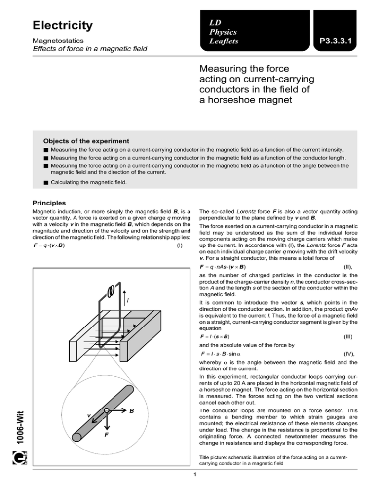
LD Physics Leaflets Electricity Magnetostatics Effects of force in a magnetic field P3.3.3.1 Measuring the force acting on current-carrying conductors in the field of a horseshoe magnet Objects of the experiment ■ Measuring the force acting on a current-carrying conductor in the magnetic field as a function of the current intensity. ■ Measuring the force acting on a current-carrying conductor in the magnetic field as a function of the conductor length. ■ Measuring the force acting on a current-carrying conductor in the magnetic field as a function of the angle between the magnetic field and the direction of the current. ■ Calculating the magnetic field. Principles Magnetic induction, or more simply the magnetic field B, is a vector quantity. A force is exerted on a given charge q moving with a velocity v in the magnetic field B, which depends on the magnitude and direction of the velocity and on the strength and direction of the magnetic field. The following relationship applies: F = q ⋅ (v ×B ) The so-called Lorentz force F is also a vector quantity acting perpendicular to the plane defined by v and B. The force exerted on a current-carrying conductor in a magnetic field may be understood as the sum of the individual force components acting on the moving charge carriers which make up the current. In accordance with (I), the Lorentz force F acts on each individual charge carrier q moving with the drift velocity v. For a straight conductor, this means a total force of (I) F = q ⋅ nAs ⋅ (v × B ) (II), as the number of charged particles in the conductor is the product of the charge-carrier density n, the conductor cross-section A and the length s of the section of the conductor within the magnetic field. I It is common to introduce the vector s, which points in the direction of the conductor section. In addition, the product qnAv is equivalent to the current I. Thus, the force of a magnetic field on a straight, current-carrying conductor segment is given by the equation F = I ⋅ (s × B ) (III) and the absolute value of the force by F = I ⋅ s ⋅ B ⋅ sinα (IV), whereby α is the angle between the magnetic field and the direction of the current. 1006-Wit In this experiment, rectangular conductor loops carrying currents of up to 20 A are placed in the horizontal magnetic field of a horseshoe magnet. The force acting on the horizontal section is measured. The forces acting on the two vertical sections cancel each other out. – v The conductor loops are mounted on a force sensor. This contains a bending member to which strain gauges are mounted; the electrical resistance of these elements changes under load. The change in the resistance is proportional to the originating force. A connected newtonmeter measures the change in resistance and displays the corresponding force. B F Title picture: schematic illustration of the force acting on a currentcarrying conductor in a magnetic field 1 P3.3.3.1 LD Physics Leaflets Setup and carrying out the experiment Notes: Apparatus 1 Horseshoe magnet with yoke . . . . . . . 510 21 1 Force sensor . . . . . . . . . . . . . . . . 1 Set conductor loops for force measurement 1 Support for conductor loops . . . . . . . . 1 Newtonmeter . . . . . . . . . . . . . . . . 1 Multicore connecting cable, 6-pole . . . . 314 261 516 34 314 265 314 251 501 16 1 High current power supply . . . . . . . . . 521 55 1 Stand base, small, V-shape . . . . . . . . 1 Stand rod, 47 cm . . . . . . . . . . . . . 1 Leybold multiclamp . . . . . . . . . . . . 300 02 300 42 301 01 As the measurement quantity is very small, the measurement is easily affected by ambient interfering effects: Avoid shocks, drafts and temperature variations in the vicinity. The newtonmeter must warm up for at least 15 minutes before starting the experiment: Switch on the newtonmeter with the force sensor connected using the mains switch on the rear of the device. Subject the support and the conductor loops to loads of 20 A only for brief periods at a time (just a few minutes). The magnetic field of the horseshoe magnet is not homogeneous: For all measurements, center the conductor loop between the two arms of the magnet so that the effect of the magnetic field is as uniform as possible. Connecting leads with conductor cross-section 2.5 mm2 – Set up the experiment as shown in Fig. 1. – To avoid short-circuits, make sure that the non-insulated cable sections of the support for conductor loops do not touch. – Set the measuring range switch (d) on the newtonmeter to 2000. The experiments are carried out using only the conductor loops without narrow section. The easiest way to set the current is to use only the current control knob (b). The voltage control knob (a) is turned all the way to the right. a) Measuring as a function of current: – Turn the current control knob (b) all the way to the left and the voltage control knob (a) all the way to the right. Then switch on the high current power supply. 314 OU TPUT 261 Experiment setup for measuring the force acting on current-carrying conductors in a magnetic field First, attach the 8 cm wide conductor loop to the force sensor. KAFT FORC-SEN E SESOR NSOR Fig. 1 – V a A b mN N kN COMPENSATION RESET 240W P max 0...24V 0...20A U max SET c max 20 INPUT - + 200 OUTPUT 2000 FAST AUTORANGE SENSOR +- 2 V d SLOW 314 251 521 55 2 P3.3.3.1 LD Physics Leaflets – To compensate the zero point of the newtonmeter, select the SET position with the COMPENSATION switch (c). – Set up the horseshoe magnet so that the magnetic field and the conductor section are parallel. – Using the current control knob (b), increase the current to 20 A in steps of 2 A; for each current level, read off the force from the newtonmeter and write these values in your experiment log. – To compensate the zero point of the newtonmeter, select the SET position with the COMPENSATION switch (c). – Set the current level I = 10 A. – Turn the magnet through 360° in steps of 30° and read off the force from the newtonmeter for each angle. – Set the current to 0 A and check the zero point of the force display. – Set the current to I = 0 A and check the zero point of the force display. b) Measuring as a function of the conductor length: – Attach the 4 cm wide conductor loop to the force sensor. – To compensate the zero point of the newtonmeter, select the SET position with the COMPENSATION switch (c). – Set the current level I = 20 A, read off the force from the newtonmeter and write this value in your experiment log. a) Measuring as a function of current: – Set the current to I = 0 A and check the zero point of the force display. Table 1: Force F as a function of the current I (s = 8 cm) – Repeat the measurement for the 2 cm and the 1 cm conductor. Measuring example and evaluation c) Measuring as a function of the angle between the magnetic field and the direction of the current: Recommendation: to compensate for the non-homogeneous nature of the magnetic field, and to set the proper rotational angle, make a template (see Fig. 2). This makes positioning the horseshoe magnet easier and more accurate. – Turn the current control knob all the way to the left and attach the 4 cm wide conductor loop to the force sensor. – Place the template underneath the conductor loop so that the center of the template is exactly underneath the midpoint of the horizontal conductor section and one of the template lines is parallel to this conductor section. Fig. 2 I A F mN 0 2 4 6 8 10 12 14 16 18 20 0.0 4.5 9.3 13.5 18.0 22.5 27.0 31.4 35.9 40.4 45.6 F mN 40 Using the template as an aid in positioning the horseshoe magnet 30 20 10 0 0 5 10 15 20 I A Fig. 3 Force F acting on a current-carrying conductor as a function of the current I (cf. Table 1) In the graph in Fig. 3, the measured values show a close approximation of a straight line with the slope mN F = 2.26 A I 30° Given that sin90° = 1, equation (IV) gives us the following value for the magnetic field: B= 8 cm F 2.26 mN = = 28.5 mT I ⋅ s A ⋅ 0.08 m The linear relationship between the force and the current for a constant conductor length formulated in equations (III) and (IV) is confirmed. 3 P3.3.3.1 LD Physics Leaflets b) Measuring as a function of the conductor length: c) Measuring as a function of the angle between the magnetic field and the direction of the current: Table 2: Force F as a function of the length s (I = 20 A) Table 3: Force F as a function of the angle α (s = 4cm, I = 10A) s cm F mN 8 4 2 1 45.6 23.0 11.7 6.2 F mN α 0.0 5.6 9.9 11.6 10.4 6.3 0.1 -5.8 -9.9 -11.5 -10.1 -6.0 0.1 0 30 60 90 120 150 180 210 240 270 300 330 360 F mN 40 30 20 F mN 10 10 0 0 2 4 6 8 s cm Fig. 4 0 Force F acting on a current-carrying conductor as a function of the conductor length s (cf. Table 2) -10 In Fig. 4, the measured values are also a close approximation of a straight line through the origin with the slope 0o 60o 120o 180o 240o 300o 360o α mN F = 572 m s For the magnetic field, we obtain the value B= F 572 mN = = 28.6 mT s ⋅ I m ⋅ 20 A The linear relationship between the force and the conductor length for a constant current formulated in (III) and (IV) is confirmed. Fig. 5 Force F acting on a current-carrying conductor as a function of the angle α between the magnetic field and the direction of current (cf. Table 3) The measured values in Fig. 5 are a close approximation of a sine curve calculated using (IV) for a magnetic field B = 28.5 mT. LD DIDACTIC GmbH · Leyboldstrasse 1 · D-50354 Hürth · Phone (02233) 604-0 · Telefax (02233) 604-222 · E-mail: info@ld-didactic.de © by LD DIDACTIC GmbH Printed in the Federal Republic of Germany Technical alterations reserved


