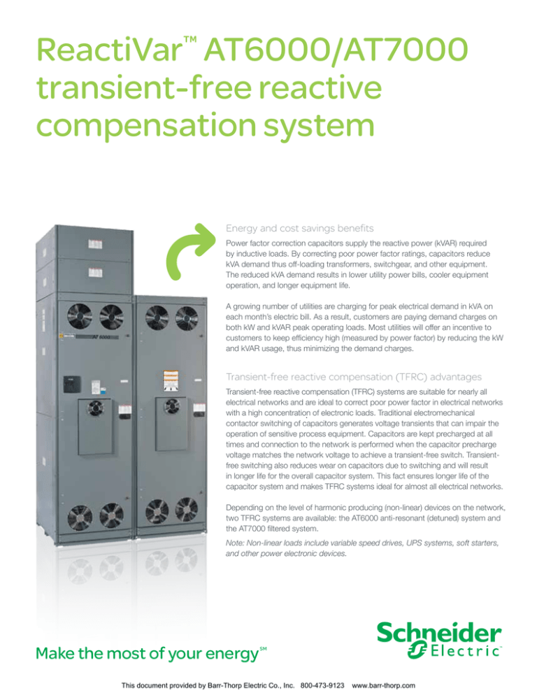
ReactiVar™ AT6000/AT7000
transient-free reactive
compensation system
Energy and cost savings benefits
Power factor correction capacitors supply the reactive power (kVAR) required
by inductive loads. By correcting poor power factor ratings, capacitors reduce
kVA demand thus off-loading transformers, switchgear, and other equipment.
The reduced kVA demand results in lower utility power bills, cooler equipment
operation, and longer equipment life.
A growing number of utilities are charging for peak electrical demand in kVA on
each month’s electric bill. As a result, customers are paying demand charges on
both kW and kVAR peak operating loads. Most utilities will offer an incentive to
customers to keep efficiency high (measured by power factor) by reducing the kW
and kVAR usage, thus minimizing the demand charges.
Transient-free reactive compensation (TFRC) advantages
Transient-free reactive compensation (TFRC) systems are suitable for nearly all
electrical networks and are ideal to correct poor power factor in electrical networks
with a high concentration
. of electronic loads. Traditional electromechanical
contactor switching of capacitors generates voltage transients that can impair the
operation of sensitive process equipment. Capacitors are kept precharged at all
times and connection to the network is performed when the capacitor precharge
voltage matches the network voltage to achieve a transient-free switch. Transientfree switching also reduces wear on capacitors due to switching and will result
in longer life for the overall capacitor system. This fact ensures longer life of the
capacitor system and makes TFRC systems ideal for almost all electrical networks.
Depending on the level of harmonic producing (non-linear) devices on the network,
two TFRC systems are available: the AT6000 anti-resonant (detuned) system and
the AT7000 filtered system.
Note: Non-linear loads include variable speed drives, UPS systems, soft starters,
and other power electronic devices.
Make the most of your energy
SM
This document provided by Barr-Thorp Electric Co., Inc. 800-473-9123
www.barr-thorp.com
Product specifications
•Transient-free switching of capacitor steps within
10 seconds
Capacitor dielectric
•Electronic switching elements yield an unlimited
number of switching operations
Metalized polypropylene film;
no liquid dielectrics
Internal connection
3-phase, Delta
•Sophisticated power factor controller options
Tolerance on capacitance
0% / +15%
•LCD display on controller displays actual power
factor, alarms, number of steps energized, and
much more
Discharge mechanism
Polycarbonate resistor; 1 per phase
Discharge time
One minute to less than 50 V
•Heavy duty capacitor element provides
superior performance
Expected life
(5% reduction in rated kVAR
near the end of life is typical)
≥130,000 hours at nominal voltage and
rated current, 0% THD(V)
Rated voltage (U n)
208 V, 240 V, 380 V, 400 V,
415 V, 480 V, 600 V
Rated frequency
60 Hz, 50 Hz (option)
Insulation level
3 kV rms/15 kV crest
Interrupting rating
– Maximum
50 kA AIC symmetrical at 600 V
65 kA AIC symmetrical at 480 V
AT6000/AT7000: Selection guide
Continuous overvoltage
1.1 x U n
There are special considerations when applying
capacitors to a network containing highly cyclical or
harmonic-producing loads. The following information
is needed to ensure proper equipment selection:
•Twelve months of utility billing information
Continuous overcurrent
1.35 x I n
Maximum allowed
Harmonic current (I h)
1.05 x I n
Maximum allowed
harmonic voltage (v h)
1.05 x V n
Ambient temperature range
-10° C to +40° C (14° F to +104° F)
> Highest mean: 24 hours
+40° C (+104° F)
> Highest mean: 1 year
+35° C (+95° F)
Other conditions
Consult Schneider Electric™
Altitude
≤ 1800 m (6000 ft) without de-rating
Standards
CSA C22.2 No. 190, UL 810
Paint finish
ASA 49 N1, ASA 61 N3R
Enclosure
NEMA® Type 1, 3R
•QED switchboard-style section constructed of
12-gauge steel frame covered with removable
16-gauge steel panels
•Standard section dimension of 30 in. wide
x 36 in. deep x 91.5 in. high
•Capacity available up to 1350 kVAR at 480 V
•Location of utility metering
•A single-line diagram of the network showing
nature of loads (Examples: 150 HP FVNR starters,
200 HP VFD, etc.)
•Transformer(s) kVA rating, percent impedance
(%Z), primary and secondary voltages
•Harmonic spectrum of current and voltage or TDD*
and THD(V)** reading at point of compensation
•Size and location of any existing capacitors
* TDD: Total demand distortion (current)
** THD(V): Total harmonic distortion (voltage)
For more information
888-778-2733
www.schneider-electric.us/go/services
Schneider Electric USA
1415 South Roselle Road
Palatine, IL 60067
Tel: 847-397-2600
Fax: 847-925-7500
www.schneider-electric.us
This document has been
printed on recycled paper.
Document Number 5870HO1101
This document provided by Barr-Thorp Electric Co., Inc. 800-473-9123
www.barr-thorp.com
October 2011
©2011 Schneider Electric. All Rights Reserved. Schneider Electric, ReactiVar, and Make the most of your energy are trademarks owned
by Schneider Electric Industries SAS or its affiliated companies. All other trademarks are property of their respective owners. 998-4774
Product features


