24-VOLT INPUT DC-DC CONVERTERS - Wilmore Electronics Co., Inc.
advertisement

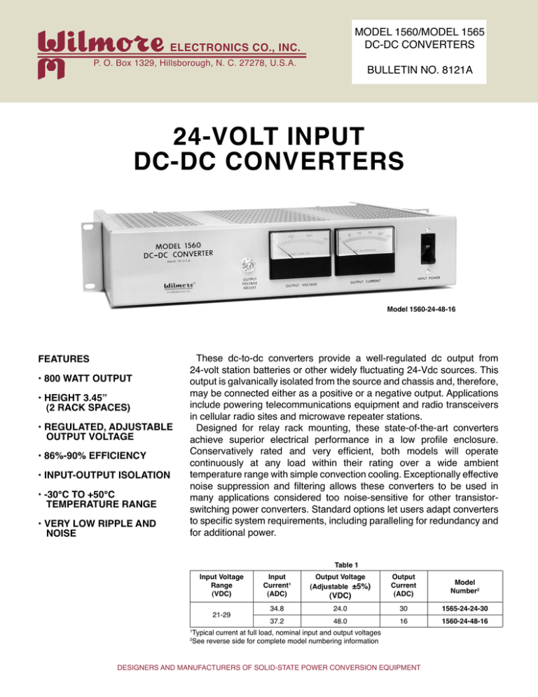
MODEL 1560/MODEL 1565 DC-DC CONVERTERS ELECTRONICS CO., INC. P. O. Box 1329, Hillsborough, N. C. 27278, U.S.A. BULLETIN NO. 8121A 24-VOLT INPUT DC-DC CONVERTERS Model 1560-24-48-16 FEATURES • 800 WATT OUTPUT • HEIGHT 3.45” (2 RACK SPACES) • REGULATED, ADJUSTABLE OUTPUT VOLTAGE • 86%-90% EFFICIENCY • INPUT-OUTPUT ISOLATION • -30°C TO +50°C TEMPERATURE RANGE • VERY LOW RIPPLE AND NOISE These dc-to-dc converters provide a well-regulated dc output from 24-volt station batteries or other widely fluctuating 24-Vdc sources. This output is galvanically isolated from the source and chassis and, therefore, may be connected either as a positive or a negative output. Applications include powering telecommunications equipment and radio transceivers in cellular radio sites and microwave repeater stations. Designed for relay rack mounting, these state-of-the-art converters achieve superior electrical performance in a low profile enclosure. Conservatively rated and very efficient, both models will operate continuously at any load within their rating over a wide ambient temperature range with simple convection cooling. Exceptionally effective noise suppression and filtering allows these converters to be used in many applications considered too noise-sensitive for other transistorswitching power converters. Standard options let users adapt converters to specific system requirements, including paralleling for redundancy and for additional power. Input Voltage Range (VDC) 21-29 Table 1 Input Current1 (ADC) Output Voltage (Adjustable ±5%) (VDC) Output Current (ADC) Model Number2 34.8 24.0 30 1565-24-24-30 37.2 48.0 16 1560-24-48-16 Typical current at full load, nominal input and output voltages 2 See reverse side for complete model numbering information 1 DESIGNERS AND MANUFACTURERS OF SOLID-STATE POWER CONVERSION EQUIPMENT SPECIFICATIONS Top View Input Voltage 21 Vdc to 29 Vdc (24 Vdc nominal) Output Voltage and Current The nominal output voltage, the adjustable output voltage range, and output current for standard models are shown in Table 1. Output Voltage Regulation Versus line: ±0.1% Versus load: ±0.5% Output Voltage Ripple and Noise 5 millivolts rms (typical) 50 millivolts peak-to-peak (typical) Isolation and Grounding Mutual electrical isolation is provided between the input circuit, the output circuit, and chassis ground. Protection Protection against overloads, shortcircuits and output overvoltages is provided electronically. Recovery to normal operating conditions is automatic upon removal of the overload or short-circuit fault. Following an overvoltage shutdown, input power to the converter must be removed and reapplied to resume converter operation. Protection against accidental reversal of the dc inputvoltage polarity during installation is provided by a shunt diode working in conjunction with the front-panel circuit breaker. Ambient Temperature Range Operating: -30ºC to +50ºC (convection cooling) Storage: -40ºC to +95ºC Efficiency The efficiency reaches 86% at approximately 15% of full load and remains above 86% for most of the load range. The no-load input current is approximately 250 milliamperes. Heat dissipation is approximately 400 BTU/hour. Rear View (Cover Plate Removed) All dimensions in inches Fig. 1 Model 1560/Model 1565 overall dimensions Front-Panel Controls and Indicators A combination circuit breaker and ON/OFF switch is provided for input power. A potentiometer shaft with locking nut is provided to adjust the output voltage level. A voltmeter and ammeter display the dc output. Physical Characteristics Refer to Fig. 1 for overall dimensions. Weight is less than 18 pounds. Brackets are provided for 19-inch or 23-inch relay rack mounting. A cover panel protects the recessed rear-panel wiring connections. STANDARD OPTIONS1 • Output series diode for parallelredundant operation of multiple converters • Auxiliary Form C contacts for remote indication of improper output (converter fail) • Balanced load sharing between converters being paralleled for additional power Some options may affect voltage regulation, ripple and noise, and efficiency specifications. 1 MODEL NUMBERING INFORMATION The Model 1560 and Model 1565 converters are identified by four numbers. In sequence, these give the basic model number, the nominal input voltage, the nominal output voltage, and the maximum load current. Standard options are specified by an additional suffix: M1 designates paralleling diode plus auxiliary contacts, M2 designates load sharing and M3 combines paralleling diode, auxiliary contacts, and load sharing. For example, Model 1560-24-48-16-M3 is a 24-volt to 48-volt converter with a 16-ampere maximum load rating. It is provided with paralleling diode, auxiliary contacts and load sharing capability. OTHER WILMORE PRODUCTS For information about other Wilmore dc-to-dc converters or for information about other power-conditioning products such as switching power supplies, dc-to-ac inverters, and uninterruptible power systems, please contact our sales department. Information provided in this bulletin is subject to change without notice. WILMORE ELECTRONICS COMPANY, INC. P. O. Box 1329, Hillsborough, N. C. 27278 • Telephone (919) 732-9351 • FAX (919) 732-9359 www.wilmoreelectronics.com


