FGD3 Flammable Specification
advertisement

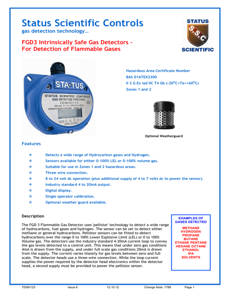
Status Scientific Controls gas detection technology… FGD3 Intrinsically Safe Gas Detectors – For Detection of Flammable Gases Hazardous Area Certificate Number BAS 01ATEX2300 II 2 G Ex iad IIC T4 Gb (-20OC<Ta<+60OC) Zones 1 and 2 Optional Weatherguard Features v Detects a wide range of Hydrocarbon gases and Hydrogen. v Sensors available for either 0-100% LEL or 0-100% volume gas. v Suitable for use in Zones 1 and 2 hazardous areas. v Three wire connection. v 8 to 24 volt dc operation (plus additional supply of 4 to 7 volts dc to power the sensor). v Industry standard 4 to 20mA output. v Digital display. v Single operator calibration. v Optional weather guard available. Description The FGD 3 Flammable Gas Detector uses 'pellistor' technology to detect a wide range of hydrocarbons, fuel gases and hydrogen. The sensor can be set to detect either methane or general hydrocarbons. Pellistor sensors can be fitted to detect hydrocarbons over the range 0 to 100% Lower Explosive Limit (LEL) or 0 to 100% Volume gas. The detectors use the industry standard 4-20mA current loop to convey the gas levels detected to a control unit. This means that under zero gas conditions 4mA is drawn from the supply, and under full scale gas conditions 20mA is drawn from the supply. The current varies linearly for gas levels between zero and full scale. The detector heads use a three-wire connection. While the loop current supplies the power required by the detector head electronics within the detector head, a second supply must be provided to power the pellistor sensor. TD06/123 Issue 6 12.10.12. Change Note: 1788 EXAMPLES OF GASES DETECTED METHANE HYDROGEN PROPANE BUTANE ETHANE PENTANE HEXANE OCTANE ETHANOL IPA SOLVENTS Page 1 Marine Version A marine version of the FGD3 is also available. This version is housed in a cast aluminium enclosure to provide higher RFI immunity where high power portable radios are used in the close confines of a vessel. The enclosure is plated and painted in order to withstand the harsh salt spray environment of the marine industry. The digital display is fitted with a sliding stainless steel front cover which remains over the display window when not being viewed thereby maintaining the RFI shielding properties of the enclosure during normal operation. Weather Guard An optional weather guard is available for installations exposed to the atmosphere or contaminants and is also suitable for use in other areas where hosing down takes place. The weather guard reduces the possibility of water or other contaminants entering into the gas sensor thereby improving the overall reliability of the gas detector in harsh environments. The weather guard is attached with tamperproof screws to ensure that it is not inadvertently removed. Collector Cone A collector cone is available which can be fitted around the sensor inlet in order to concentrate any gas present around the sensor and hence improve the detection ability. Mounting brackets are also available. Mounting Kits A Swivel Mounting Bracket and Ceiling Mounting Kit is available for use with this range of gas detectors. In addition, a duct mounting kit is also available, please contact Status Scientific Controls to discuss your particular application. Gas Detector - Ordering Details (add suffix ‘ –US’ for USA) Stock No. Description SS415 FGD3 Flammable (0-100% Volume) Detector Head SS416 FGD3 Flammable (0-100% LEL) Detector Head SS417 FGD3 Flammable (0-100% LEL) Detector Head for Fuels Note – Standard gland entry is 20mm x 1.5mm pitch thread. For USA and Canada, gland entry is ½” NPT thread. Accessories - Ordering Details Stock No. Description SS359 Intrinsically Safe Output Module – see page 3 SS374 Swivel Mounting Bracket SS375 Ceiling Mounting Bracket SS429 Collector Cone SS475 FGD3 Weatherguard TD06/123 Issue 6 12.10.12. Change Note: 1788 Page 2 TYPICAL INSTALLATION USING STATUS SCIENTIFIC CONTROLS MCU CONTROL UNIT TYPICAL INSTALLATION USING AN OEM CONTROL PANEL Status Intrinsically Safe Output Module Type SS359 MCU Control unit fitted with I.S. Output Module Type FGDIO + 24v D.C. 0V 4-20 mA Control unit or PLC with 24V output and 4-20mA input OEM CONTROL PANEL Safe area Safe area Hazardous area Hazardous area FGD3 Flammable Gas Detector FGD3 Flammable Gas Detector The Intrinsically Safe Output Module shown below provides the necessary interface between a nonintrinsically safe, mains powered system (as shown above, right) and an FGD3 Flammable Gas Detector. Note that an intrinsically safe earth must be connected to the module to ensure safety. Intrinsically Safe Output Module Type SS359 Specification Inputs Temperature Humidity range Operating pressure Internal Resistance Source Resistance Intrinsically Safe Outputs Certificate No. Code Zones TD06/123 14-28vDC Current Loop 12-24V Sensor Supply -20 - +40°C 0-95% RH non-condensing Ambient + or – 10% Current Loop : 270R ±5% Sensor Supply : 12.0R ±5% Terminal Uo Io Po s 1&2 28V .112A .8W 3&4 7.5V .66A 1.24W Baseefa 03ATEX0590X II (1) G [EEx ia] IIC 1 or 2 Issue 6 12.10.12. DIN rail mounting Change Note: 1788 Page 3 Specification Material : Plastic (ABS and Polycarbonate blending) Marine Version – Cast Aluminium Alloy Cable entry : 1 x M20 or ½” NPT Dimensions : 122 x 122 x 75 mm Weights : Plastic Version (excluding weatherguard) – 660grams Marine Version (excluding weatherguard) – 1Kg Weatherguard – 225 grams Display type : LCD Gas Types : Hydrocarbons including Methane, Hydrogen, Ammonia Operating voltages : 8 to 28V dc (for 4 to 20 mA signal) 5.8 to 7.5V dc (for sensor supply) : 0mA - open circuit 2mA - fault 4mA - zero gas 20mA - full scale gas 22mA - over-range : Signal - 560 ohms at 24vdc Sensor - 19 ohms at 7.5vdc Sensor Type : Pellistor (catalytic bead) Measurement ranges : 0-100% LEL (5% vol CH4), 0-100% Volume Response time : T90 < 10 sec (Methane) Measurement Resolution : 1% LEL IP rating : Enclosure IP66, Sensor IP65 Operating Temperature : - 20 to +40 Storage temperature : - 20 to +50 O C Humidity Range : 0 to 95% RH non-condensing Operating Pressure : Ambient + or - 10% Output Signal Max. Cable Loop Resistance O C Hazardous Area Certification Certificate Number : Standards : Zones : BAS 01ATEX2300, Code II 2G Ex iad IIC T4 Gb (-20OC<Ta<+60OC) EN 60079-0:2009 EN 60079-1:2007 EN 60079-11:2007 1&2 Designed and Manufactured in the UK Status Scientific Controls Ltd www.status-scientific.com Cambridge Sensotec Ltd 29 Stephenson Road St Ives, Cambs PE27 3WJ United Kingdom Tel: +44 (0)1480 462142 sales@cambridge-sensotec.co.uk www.cambridge-sensotec.co.uk TD06/123 Issue 6 12.10.12. Change Note: 1788 Page 4


