ECE 391: Transmission Lines Homework Assignment #6
advertisement
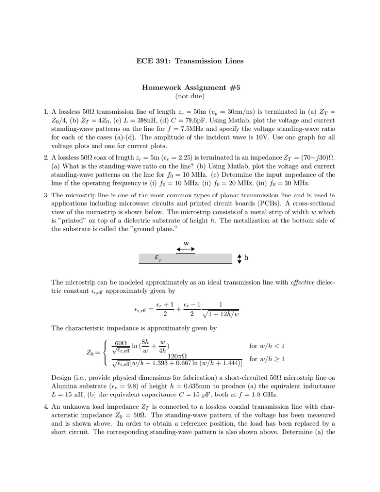
ECE 391: Transmission Lines Homework Assignment #6 (not due) 1. A lossless 50Ω transmission line of length zr = 50m (vp = 30cm/ns) is terminated in (a) ZT = Z0 /4, (b) ZT = 4Z0 , (c) L = 398nH, (d) C = 79.6pF. Using Matlab, plot the voltage and current standing-wave patterns on the line for f = 7.5MHz and specify the voltage standing-wave ratio for each of the cases (a)-(d). The amplitude of the incident wave is 10V. Use one graph for all voltage plots and one for current plots. 2. A lossless 50Ω coax of length zr = 5m (ǫr = 2.25) is terminated in an impedance ZT = (70−j30)Ω. (a) What is the standing-wave ratio on the line? (b) Using Matlab, plot the voltage and current standing-wave patterns on the line for f0 = 10 MHz. (c) Determine the input impedance of the line if the operating frequency is (i) f0 = 10 MHz, (ii) f0 = 20 MHz, (iii) f0 = 30 MHz. 3. The microstrip line is one of the most common types of planar transmission line and is used in applications including microwave circuits and printed circuit boards (PCBs). A cross-sectional view of the microstrip is shown below. The microstrip consists of a metal strip of width w which is ”printed” on top of a dielectric substrate of height h. The metalization at the bottom side of the substrate is called the ”ground plane.” The microstrip can be modeled approximately as an ideal transmission line with effective dielectric constant ǫr,eff approximately given by ǫr,eff = ǫr + 1 ǫr − 1 1 p + 2 2 1 + 12h/w The characteristic impedance is approximately given by Z0 = 8h w √60Ω ln ( + ) ǫr,eff √ w 4h 120πΩ ǫr,eff [w/h + 1.393 + 0.667 ln (w/h + 1.444)] for w/h < 1 for w/h ≥ 1 Design (i.e., provide physical dimensions for fabrication) a short-circuited 50Ω microstrip line on Alumina substrate (ǫr = 9.8) of height h = 0.635mm to produce (a) the equivalent inductance L = 15 nH, (b) the equivalent capacitance C = 15 pF, both at f = 1.8 GHz. 4. An unknown load impedance ZT is connected to a lossless coaxial transmission line with characteristic impedance Z0 = 50Ω. The standing-wave pattern of the voltage has been measured and is shown above. In order to obtain a reference position, the load has been replaced by a short circuit. The corresponding standing-wave pattern is also shown above. Determine (a) the voltage standing-wave ratio when the line is terminated in impedance ZT , (b) the wavelength, (c) the unknown load impedance ZT ; (d) Plot the corresponding current versus position z ′ for impedance ZT ; (e) What percentage of the time-average power carried to the termination is dissipated in the load impedance ZT ? 5. A 2 meter long, lossless, air-spaced transmission line having characteristic impedance Z0 = 50Ω is terminated in impedance ZT = (40 + j50)Ω at an operating frequency of 200 MHz. Determine the input impedance at the operating frequency. What is the input impedance if the frequency is changed to 300 MHz (assume that the terminating impedance is unchanged)? 6. (a) The voltage amplitude of a sinusoidal wave at the input of a 200m long transmission line is Vin = 5V. The far end of the line is matched (no reflected waves are excited) and the voltage is measured as Vout = 3V. What is the attenuation in (i) dB/m, (ii) Np/m? (b) A coaxial cable has a specified attenuation constant of α = 0.05dB/m. Specify the attenuation constant in (i) dB/cm, (ii) Np/m, (iii) dB/100ft. How much is the voltage amplitude of a single traveling sinusoidal wave attenuated after 100 meters? Give your answer in %, dB, and nepers. 7. The following data are specified at f = 200KHz for a given transmission line. Z0 = (52 − j0.4)Ω α = 5 × 10⁻³ dB/m β = 8.3776 × 10⁻³ rad/m Determine the R, L, G, C transmission line parameters, wavelength, and phase velocity. 8. A lossless 600Ω open-wire transmission line of length zr = 500m (ǫr = 1) is terminated in an impedance ZT = (400− j300)Ω. The circuit is operated at f = 1 MHz. (a) What is the standingwave ratio on the line? (b) Plot the voltage and current standing-wave patterns (magnitude) on the line. (c) Determine the input impedance of the line. 9. A 500 m long low-loss coaxial cable with characteristic impedance Z0 = 50Ω is terminated in ZT = 50Ω, as shown below. The attenuation constant of the cable is specified as 20dB/km at f = 80MHz. What is the average power dissipated in the load ZT at f = 80MHz? How much power is lost in the cable? 80MHz ? How much power is lost in the cable? 50Ω 10Vrms l = 500m Z 0 = 50Ω Z T = 50Ω α = 20dB/km z' 0 10. A load impedance ZT = (100 − j50)Ω is connected to a source through a wavelength long lossless transmission line of characteristic impedance Z0 = 50Ω, as shown below. = Determine the average power delivered to the load by the generator. How does your answer change if the length of the transmission line is 1.18λ? λ
