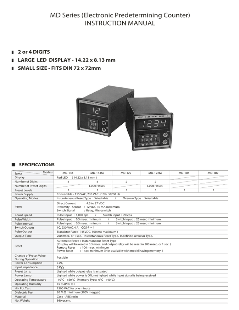
MD Series (Electronic Predetermining Counter)
INSTRUCTION MANUAL
2 or 4 DIGITS
LARGE LED DISPLAY - 14.22 x 8.13 mm
SMALL SIZE - FITS DIN 72 x 72mm
SPECIFICATIONS
Models
Specs
Display
Number of Digits
Number of Preset Digits
Preset Levels
Power Supply
Operating Modes
Input
Count Speed
Pulse Width
Pulse Interval
Switch Output
Pulse Output
Output Time
Reset
Change of Preset Value
During Operation
Power Consumption
Input Impedance
Preset Lamp
Power Lamp
Operating Temperature
Operating Humidity
Hi - Pot Test
Dielectric Test
Material
Net Weight
MD-144
MD-144M
MD-122
MD-122M
Red LED ( 14.22 x 8.13 mm )
4
4
2
2
1,000 Hours
1,000 Hours
1
1
1
1
Convertible - 115 VAC, 230 VAC ±10% 50/60 Hz
Instantaneous Reset Type : Selectable
/
Overrun Type : Selectable
Direct Current
Proximity - Sensor
Switch Signal
: 4.5 to 27 VDC
: 12 VDC 30 mA maximum
: Relay, Microswitch
Pulse Input : 1,000 cps
/
Switch input : 20 cps
Pulse Input : 0.5 msec. mnimum
/
Switch input : 25 msec minimum
Pulse Input : 0.5 msec. mnimum
/
Switch input : 25 msec minimum
1C, 230 VAC, 4 A COS = 1
Transistor Rated ( 45VDC, 100 mA maximum )
200 msec. or 1 sec. - Instantaneous Reset Type. Indefinite-Overrun Type.
Automatic Reset : Instantaneous Reset Type
( Display will be reset in 0.3 msec. and output relay will be reset in 200 msec. or 1 sec. )
Remote Reset : 100 msec. minimum
Power Reset
: 1 sec. minimum ( Not available with model having memory. )
Possible
4 VA
5K
Lighted while output relay is actuated
Lighted while power is ON, not lighted while input signal is being received
-10°C - +50°C (Memory Type: 0°C - +40°C)
45 to 85% RH
1500 VAC for one minute
20 M minimum (500V megger)
Case - ABS resin
560 grams
MD-104
MD-102
1
1
FEATURES
· Line Seiki predetermining counters-highly reliable and
extremely versatile.
· Large , high-brightness LED’s.
· Protected against accidental Tripping of output relay.
· Fits DIN panel opening.
· Built-in power supply module.
· Switch or pulse input and output.
· Two operating modes, instantaneous reset or overrun.
· Memory circuit stores count data during power failures.
· Dustproof thumbwheel switches.
6. Operating Mode
Instantaneous Reset Type : no connection required.
Overrun Type
: Terminal 11 , connect to negative of supply.
16 and
15 and
to Terminal 3
on MD-144M or MD-122M
NOTE : Disconnect wiring to prevent battery discharge when the counter is
out of service for more than 1,000 hours. Battery is charged whenever power
is being supplied. The LED display is extinguished while MD-144M or
MD-122M is used on power failure, and the counter will not operate even
if input signal or reset signal is received.
( input signals do not consume battery energy. )
See diagram for location of terminals
17
17
2. Input
a) Pulse
Positive, regulated 4.5 VDC to 27 VDC - Terminal 4
Negative - Terminal 3
8. CAUTION
Switch input and proximity-sensor input cannot be used at the same time.
Do not apply voltage to switch input terminals or remote-reset terminals.
CONNECTIONS
b) Proximity Sensor ( 12VDC )
Positive 12 VDC - Terminal 2
Negative - Terminal 3
Output - Terminal 4
c) Switch
Terminal 1
5. Output Time
0.2 second - no connection to negative of supply
1.0 second - negative of supply - Terminal 10
Indefinite - negative of supply - Terminal 11
7. Memory
Connect Terminal 7
CONNECTIONS
1. Power Supply
· 115 VAC - Terminal
· 230 VAC - Terminal
4. Remote Reset
Terminal 5 and 6
( Counter can be reset by conventional switch, relay or microswitch. )
Sensor
Switch Input
Remote Reset
+ 12V GND
and 2
3. Output
a) Pulse ( 45 VDC at 100mA maximum ) - Terminal 9
b) Switch ( 230 VAC , 4A ; resistive load )
N. C. ( closed during count ) - Terminal 14
N. O. ( closed at present number ) - Terminal 13
COMMON - Terminal 12
1
7
(
Memory
Type Only
3
2
Memory
Signal
8
GND
5
4
9
10
11
GND
(
Open
Collector
Output
Output
1 second
BUILT - IN POWER SUPPLY
2
12 VDC
Relay
9
EXTERNAL POWER SUPPLY
5 - 30 VDC
Power Source
-
+
8
-
5 - 30 VDC
Relay
9
6
(
Output
Latched
until
reset
12
13
14
15
16
17
COM.
N. 0.
N. C.
230
115
0V
Relay Output
AC
(
OPERATING MODE
INSTANTANEOUS RESET TYPE
When the preset number is reached, output signal
0.3 sec
is provided by relay or open collector transistor.
Power
The preset number is instantaneously reset to
Preset Value
1
2
3
n-1 n
1
2
3
4
5
6
7
1
2
3
1
2
3
zero and the counter immediately begins to accept input
Input
0.2 sec or 1 sec.
signals. This type is ideally suited for controls on
Output (One Shot)
1
2
3
n-1 n
1
2
3
4
5
0
continuous production. Output relay or open collector
Display (Counts)
transistor is actuated at the preset number and it is
100 msec. minimum
Remote Reset
automatically unlatched in 0.2 or 1 second.
OVERRUN TYPE
0.3 sec
When the preset number is reached, output signal is
Power
n+1
Preset Value
1
2
3
n-1 n
n+3
n+2
n+5
n+4
1
2
3
4
provided by relay or open collector transistor. The
5
Input
counter will continue to add counts beyond the preset
Latch
Output (One Shot)
1
2
3
n-1 n
n+1 n+3
n+2
0
number until reset is made. This type is suitable to coil
1
2
3
4
5
winding applications. Output will be latched until reset
Display (Counts)
is made.
100 msec. minimum
Remote Reset
DIMENSIONS - MILLIMETERS
1 2 3 4
2
7
3
4
8
5
6
67.2
OUT
72
1
9 10 11
IN
C
8
72
107.5
N. O. N. C.
OUT
9.5
230
115
AC
0V
67.2
PANEL OPENING
14.22
( H ) 68.0 +0.7
0
SIZE OF FIGURE
8.13
( W ) 68.0 +0.7
0
LINE SEIKI CO., LTD
37-7, CHUO-CHO, 2-CHOME
MEGURO-KU, TOKYO
JAPAN 152-0001
TEL: +83-3-3716-5151
FAX: +83-3-3710-4552
E-MAIL: webtrade@line.co.jp
URL: http://www.lineseiki.com
This manual was last revised Feb. 06, 2003.
*Subject to change without prior notice.
All Rights Reserved,Copyright © 2003,LINE SEIKI CO.,LTD.

