Statement: Two dampers are connected in series. One has a
advertisement
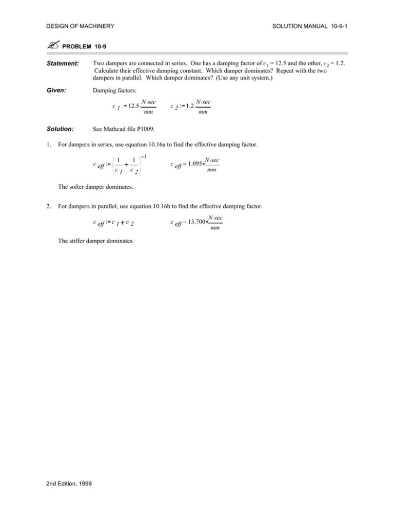
DESIGN OF MACHINERY ! SOLUTION MANUAL 10-9-1 PROBLEM 10-9 Statement: Two dampers are connected in series. One has a damping factor of c1 = 12.5 and the other, c2 = 1.2. Calculate their effective damping constant. Which damper dominates? Repeat with the two dampers in parallel. Which damper dominates? (Use any unit system.) Given: Damping factors: c1 Solution: 1. 12.5 . N .sec mm c2 1.2 . N .sec mm See Mathcad file P1009. For dampers in series, use equation 10.16a to find the effective damping factor. c eff 1 1 c1 c2 1 c eff = 1.095 N .sec mm The softer damper dominates. 2. For dampers in parallel, use equation 10.16b to find the effective damping factor. c eff c1 c2 The stiffer damper dominates. 2nd Edition, 1999 c eff = 13.700 N .sec mm DESIGN OF MACHINERY ! SOLUTION MANUAL 10-12-1 PROBLEM 10-12 Statement: A mass of m = 2.5 and a spring with k = 42 are attached to one end of a lever at a radius of 4. Calculate the effective mass and effective spring constant at a radius of 12 on the same lever. (Use any unit system.) Given: Mass: M Spring: 2.5 .kg k 42 . Radius: N mm Solution: 1. 4 .mm r2 12 .mm See Figure 10-8 and Mathcad file P1012. The effective mass and spring must have the same energy as the original. Taking the mass first and using equation 10.20b, m eff 2. r1 r1 2 .M r2 m eff = 0.278 kg To find the effective spring rate, use equation 10.21b. k eff 2nd Edition, 1999 r1 r2 2 .k k eff = 4.667 N mm DESIGN OF MACHINERY ! SOLUTION MANUAL 10-15-1 PROBLEM 10-15 Statement: Given: Refer to Figure 10-9 and Example 10-1. The data for the valve train are given below. Calculate the effective spring constant and effective mass of a single-DOF equivalent system placed on the cam side of the rocker arm. (Use ips unit system.) Tappet (solid cylinder): d tp 0.75 .in L tp 1.25 .in Pushrod (hollow cylinder): d pod 0.375 .in d pid 0.250 .in Rocker arm: w 1.00 .in h 1.50 .in a 2.00 .in b Cam shaft (cam in center): Valve spring: k vs All parts are steel: d cs 200 .lbf .in 1.00 .in 12 .in L pr 3.00 .in 3.00 .in L cs 1 Modulus of elasticity 6 30 .10 .psi E γ Spec. weight 0.3 . lbf 3 in Solution: See Figure 10-9 and Mathcad file P1015. 1. Break the system into individual elements as shown in Figure 10-9b. 2. Define the individual spring constants of each of the six elements. Cam shaft (simply-supported beam with central load): Moment of inertia Spring constant I cs k cs π .d cs 4 64 48 .E .I cs L cs 6 lbf k cs = 2.618 .10 3 in Tappet (solid cylinder): π .d tp 2 Area Spring constant A tp k tp 4 A tp .E 7 lbf k tp = 1.060 .10 in L tp Pushrod (hollow cylinder): Area Spring constant A pr k pr π . d pod 2 d pid 2 4 A pr .E L pr 5 lbf k pr = 1.534 .10 in Rocker arm (side A): Moment of inertia Spring constant Ir k ra w .h 3 12 3 .E .I r a 3 6 lbf k ra = 3.164 .10 in Rocker arm (side B): Spring constant k rb 3 .E .I r b 2nd Edition, 1999 3 5 lbf k rb = 9.375 .10 in DESIGN OF MACHINERY SOLUTION MANUAL 10-15-2 3. Damping will be neglected. 4. Determine the mass of each of the elements. Tappet (solid cylinder): Volume V tp Mass m tp A tp .L tp γ .V tp m tp = 4.291 .10 g 4 2 1 lbf .sec .in Pushrod (hollow cylinder): Volume V pr Mass m pr A pr .L pr γ .V pr 4 2 1 m pr = 5.721 .10 lbf .sec .in g Rocker arm (side A): Volume V ra Mass m ra w .h .a γ .V ra m ra = 2.331 .10 g 3 2 1 lbf .sec .in Rocker arm (side B): Volume V rb Mass m rb w .h .b γ .V rb 3 2 1 m rb = 3.497 .10 lbf .sec .in g Omit the valve and valve spring because no data are available. 5. Determine the effective mass and spring constant on either side of the rocker arm.. Left side: mL kL Right side: mR kR 6. m L = 3.332 .10 m tp m pr m ra 1 1 1 1 k cs k tp k pr k ra 1 2 1 lbf .sec .in 3 5 lbf k L = 1.368 .10 in 3 2 1 m R = 3.497 .10 lbf .sec .in m rb 1 1 1 k rb k vs k R = 199.957 lbf in Reduce the system to a single DOF. 2nd Edition, 1999 m eff mL k eff kL 2 b .m a b a 2 .k R R 2 1 m eff = 0.011 lbf .sec .in k eff = 1.372 .10 5 lbf in
