Tycho Payload Users Guide
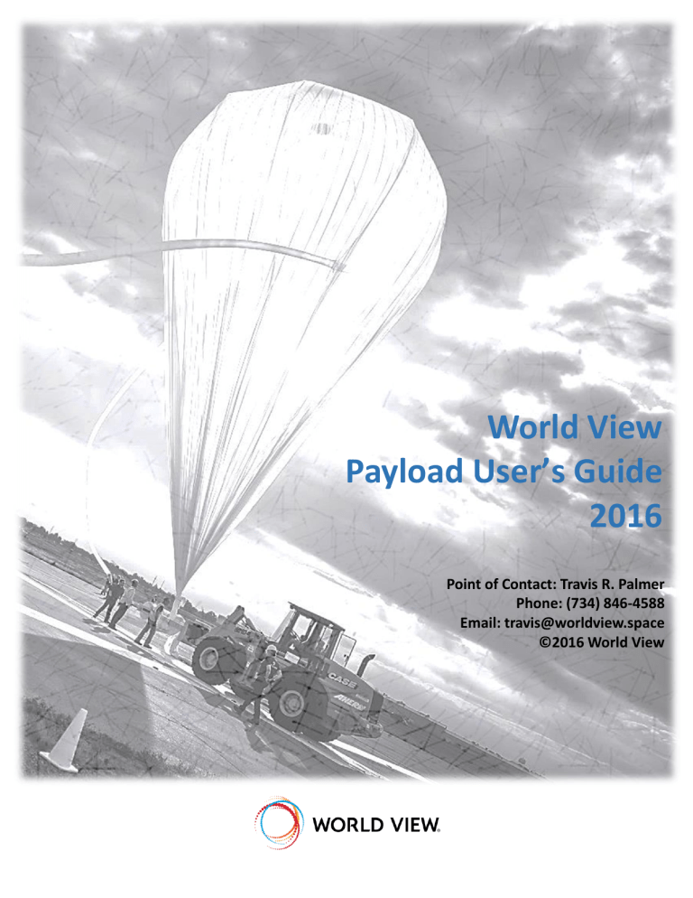
World View Payload Users Guide
World View
Payload User’s Guide
2016
Point of Contact: Travis R. Palmer
Phone: (734) 846-4588
Email: travis@worldview.space
©2016 World View
World View Payload User’s Guide
1 Introduction
Holding world records in manned and unmanned high altitude ballooning, flight operations and aerodynamic descent, World View is uniquely capable of performing a wide range of mission operations and accommodating unique payload requirements. World View is changing how the edge of space is used for research and education, from development of a concept through proposal support and successfully flying your mission on a commercially operated vehicle. If you do not find the capabilities that you are looking for in this document, please contact Travis Palmer at (734) 846-4588 or travis@worldview.space
.
This user’s guide is intended to inform payload providers who will use one of World View’s high-tech balloon systems, called Stratollites, to access the Earth’s Stratosphere.
This guide describes the capabilities and standard process by which payload providers interact with the World View team and prepare their payload for flight on our Stratollites. This guide also provides useful information regarding our Stratollite capabilities, interfaces, flight environments, logistics, and recommended payload design features that will help ensure mission success.
2 World View Stratollite Overview
World View has the capability to launch and fly payloads ranging from <1 to 4,500 kg (in development), with flight durations ranging from 5 minutes to months (capability currently in development) at target float altitudes varying from 15 to 46 km (~50,000 to 151,000 feet).
These systems share heritage with those we used for the record setting StratEx manned
balloon flights performed in October 2014 (see Figure 1).
Figure 1. StratEx Flight System
P a g e | 1
World View Payload Users Guide
Figure 2. Stratollite Architecture
World View Stratollites are comprised of their Lift Balloon
and their Stratocraft (see Figure 2). For any given flight,
these two elements are selected and tailored as needed to accommodate the payload and flight requirements. The payload(s) are mounted to or interface with the Stratollite for flight.
2.1
Stratocraft
The Stratocraft is comprised of the following sub-systems:
Stratoframe (structure)
Aerodynamic Descent System (ADS)
Avionics & Power (includes Communications)
There are a variety of configurations in which the customer provided payload can interface with the Stratollite, though our preference is to secure the payload within the
Stratoframe structure. This can reduce the amount of customization of the Stratollite required for each payload unique flight. Multiple payloads from different payload providers can be integrated into a single Stratollite for a common flight.
3 Integrated Payload Preparation & Flight Process Overview
The standard process by which payload providers interact with the World View team to prepare their payload
concludes with the de-integration and return of the payload/hardware to the payload provider. During this period, typically once every two-week status telecons are held between the World View Team and the payload provider up to integration. These telecons can be more or less frequent as needed. The following subsections describe various aspects of payload integration for our Stratollite systems.
3.1
Payload Data Package
The first step in payload integration involves the preparation of the Payload Data Package (PDP). The PDP is a standard World View document that the payload provider completes after contract signing to inform World
View of various characteristics of the payload (e.g., size, mass, general operation, safety considerations, etc.) so that flight planning and preparations can begin.
3.2
Interfaces
The second step in the process is to agree to all payload-to-Stratollite interfaces (mechanical, electrical, data, etc.). Once the interfaces are defined and agreed to, World View produces a draft Interface Control Document
(ICD) that controls these interfaces. Payload providers and World View iterate on this ICD until it is finalized. Any changes made to the interfaces after the ICD is released must be agreed to and result in a configuration controlled revision to the ICD.
P a g e | 2
World View Payload Users Guide
3.3
Payload Safety Package
Following the finalized ICD, the Payload Safety Package is generated from a standard World View form by the payload provider to answer key questions relating to payload ground and flight safety and to describe all safety measures taken to mitigate any safety risks posed by the payload systems/components (i.e., stored energy device containment).
3.4
Interface Plate & Stratollite Prep
An interface plate is often provided to the payload provider to simplify the payload integration process and aid the payload providers in the design and implementation of their structural mounting scheme. World View provides this plate shortly after the ICD is released. At this stage in the process, World View begins preparing the
Stratollite for payload integration.
3.5
Integration, Test, Operation Plan
Prior to arrival of the payload at the launch site, the payload provider must submit a complete Integration, Test, and Operation plan. A template for this plan is provided by World View. This plan is needed to ensure the World
View team is adequately informed to support the integration, test, and operation of the payload.
3.6
Hardware Readiness Review and Payload Shipment
Following receipt and review of the Integration, Test, and Operation Plan a Hardware Readiness Review (HRR) will be performed to confirm that the payload and Stratollite are ready for integration prior to flight. Upon successful completion of the HRR review, the payload provider will ship the payload to World View. The shipping
address and logistics are provided in section 9.1 of this document.
P a g e | 3
World View Payload Users Guide
Figure 3. Interactive Payload Prep & Flight Process
P a g e | 4
World View Payload Users Guide
3.7
Integration
Once a payload has arrived at the World View integration facility, a post-ship functional test is performed, followed by a test fit with the Stratollite. The payload is then prepared for integration. A final payload specific mass is measured and the payload is photographed. Once the payload is integrated it is again photographed, though now in the integrated state. The payload is then put through a bench-top functional & Radio Frequency
Interference (RFI) test in conjunction with the Stratollite systems and any other payloads that may be integrated with the Stratollite for the flight.
3.8
Flight Ready and Mission Briefing
Successful completion of the RFI test puts the Stratollite and payload(s) under configuration control, as they are now considered flight ready hardware. In parallel, all operational ground equipment and personnel are prepared for flight operations. A Mission Briefing is then performed to formally confirm readiness for flight. Regulatory and airspace operation organizations participate in the Mission Briefing along with the flight operation personnel and payload provider(s) (as available).
3.9
Flight Operations
Flight operations commence once the Mission Briefing is closed out and an acceptable launch window has been identified. Depending on the availability of the payload provider, World View will handle all payload flight operations prior to and during flight. In the event that the payload provider is unable to attend the flight, any data generated by the payload, but recorded by a World View system during the flight will be shared with the payload provider electronically after the flight.
3.10
Payload De-Integration and Return
De-integration of the payload(s) will occur within 48 hours after recovery of the Stratollite. In the event that the payload provider is unable to personally ship the payload and any support hardware, World View will assist in shipping pre-paid packages to the payload provider.
3.11
Milestone Timetable
For general planning purposes payload providers should expect the following standard milestone timeline building up to and following the execution of a flight. The durations will vary depending on payload maturity and any other factors such as non-standard services that need to be taken into account. It is also important to note that coordination with airspace controllers, airspace activities, and weather strongly factor into an actual flight date.
Table 1. Pre-Flight Milestone Table
Milestone
0.
ATP
1.
Payload Data Package Delivery to WV
2.
ICD Released to Payload
3.
Payload Safety Package Delivery to WV
4.
Payload Integration/Test/Operation Plan Delivery to
WV
5.
HRR at WV
6.
Payload Integration and Testing
7.
Weather Window Identified
Timeframe
---
ATP + 2 weeks
ATP + 4 weeks
ATP + 4 weeks
Integration – 4 weeks
Integration – 2 weeks
Flight – 1 week (start)
Flight – 1 week
P a g e | 5
World View Payload Users Guide
8.
Mission Briefing
Milestone
9.
Flight
10.
Payload De-Integration and Return Shipment
Timeframe
Flight – 1 to 3 days
---
Flight + 1 to 2 days
11.
Payload Provider Feedback Survey Returned to WV Flight + 2 weeks
4 Payload Environments
4.1
Acoustics
There no significant acoustic loads experienced during the mission profile. There are some low-level acoustic loads during balloon inflation but otherwise there are no acoustic loads of note.
4.2
Forces
4.2.1
Transportation Loads
Payloads will experience transportation loads as a function of the means of transport. See MIL-STD-810 for a range of transportation loads.
4.2.2
Launch Loads
The Stratollite launch shock loads will not normally exceed 0.5 g. Worst case launch loads will not exceed 2 g.
4.2.1
Parachute Opening Load
Sustained parachute opening loads, lasting for more than 1 second, at the payload CG, can be expected to be between 2 and 5 g’s.
The payload can swing and twist during deployment causing elevated loads at remote locations
G loads for parachute deployments are measured at the parachute risers, by measuring line tensions, they do not necessarily represent the highest load experienced at any part of the payload during parachute deployment
4.2.2
Reduced-Gravity Loads
The duration of reduced-gravity is a function of float altitude, payload mass, and drogue characteristics.
Reduced gravity durations will change substantially depending on start height.
For payloads sensitive to low gravity periods, or interested in sustained low gravity periods contact the engineer in charge for G load plots of past missions
4.2.3
Landing Speeds and Loads
Landing speeds are dependent on landing winds, canopy type and wing loading, lower speeds can be achieved with different canopies, or by adding a flaring system or guidance. Consult with the engineer in charge to get an estimate of the landing speeds for your specific landing system.
Typical forward speeds at landing are between 10 and 40 KTS
Typical vertical speeds at landing are between 5 and 20 KTS
Landing loads will be heavily dependent on terrain, parachute type, and flare characteristics
4.3
Temperatures
withstand or to protect against this temperature profile. If requested World View can provide engineering assistance in the thermal analysis and design of user payloads as a non-standard service.
P a g e | 6
World View Payload Users Guide
During ascent, convective losses will dominate the thermal payload environment. At float attitude convective losses are reduced and radiative heat transfer dominates heat transfer mechanics.
Uncovered portions of payloads will see 4-degree K
(no Earth Albedo, etc.) black space for 360 degrees of azimuth up to an elevation angle determined by balloon size and altitude. Above that elevation angle payloads will see the radiative surface of the balloon itself. It is vital that payloads be properly insulated to survive ascent through the troposphere. For sunrise or sunset launch campaigns, passage through the troposphere is thermally stressful. There are a number of low cost insulating materials which can be used to thermally protect the payload. Open cell or closed cell
Styrofoam often makes an adequate insulator.
Figure 4. International Standard Atmosphere
Thought has to be given as to how much heat is generated inside the insulated box to prevent accidentally overheating the interior of the insulated box. Consideration also has to be given to the optical properties of the exterior insulating materials or the experiment itself if uninsulated.
For sunrise launches arriving at float altitude after local sunrise there will be significant solar heating on the exterior surfaces of the insulator. A good rule of thumb is 1,400 watts of solar radiation will be applied to each square meter of exterior surface. Daytime flights need a first surface with a low absorptivity (alpha) and a high emissivity (epsilon) to prevent surface heating. There are
thermal control materials as a function of wavelength.
Table 2. Optical Properties of Commonly Used Thermal Control Materials
Material
Closed Cell Styrofoam
Open Cell Styrofoam
Flat White Exterior
House Pain
AZ-93 (AZ Tech. Inc.)
Application
Conductivity Insulator
Conductivity Insulator
Low absorptivity optical surface
Conductivity
Btu/(ft.hr.
F)
0.017
TBD
N/A
Absorptivity Emissivity
N/A
N/A
N/A
N/A
>0.9
0.15 ±0.02 0.91 ± 0.02
AZW/LA-II (AZ Tech.
Inc.)
Chemglaze A-276
SG121FD
Low absorptivity optical surface finish
Very low absorptivity optical surface finish
Low absorptivity optical surface finish
Low absorptivity optical surface
N/A
N/A
N/A
N/A
0.09 ± 0.02
0.28 ± TBD
0.91 ± 0.02
0.88 ± TBD
0.20 ± 0.04 0.88 ± 0.03
P a g e | 7
World View Payload Users Guide
Material
White Duct Tape
Application finish
Low absorptivity optical surface finish
Conductivity
Btu/(ft.hr.
F)
Absorptivity Emissivity
N/A TBD TBD
Figure 5. Optical Properties of Thermal Control Materials
A commonly used, low cost approach to balloon thermal insulation is to insulate the item with Styrofoam and cover the Styrofoam with Tyvek™ or similar tape. Although not ideal from a thermal engineering perspective this approach has been used for decades as an inexpensive, easily fabricated, stratospheric balloon equipment thermal insulation technique. Thermal design is one of the most challenging aspects of balloon payload preparation for flight and care must be given to proper thermal control to ensure the payload is not damaged by the extreme cold of the troposphere and stratosphere, or the solar illumination for day time flight.
4.4
Pressure
designed to withstand this pressure profile with a typical assumed average ascent rate approximately 5.2 m/sec.
Payloads that contain high voltage (>100V) power supplies must be designed to prevent electric discharge or arcing (Paschen’s Law). World View can provide engineering support to payload designers developing high voltage power supplies. Re-pressurization during descent should be considered by payload providers.
4.5
Humidity
Humidity environments for balloon payloads are driven by local weather conditions at the launch site. There is no on-pad humidity control for payloads. Humidity control within the payload build up area will be
P a g e | 8
World View Payload Users Guide approximately 50%. Electrostatic discharge precautions should be taken while working in the World View integration facility and payload providers are encouraged to use the ESD safe work area in the facility.
4.6
Vibration
There are no significant vibration loads on balloon payloads in flight. As discussed earlier there are transportation, launch, chute opening, and landing loads to be considered in payload structural designs but no significant random or sine vibration loads.
For consideration by payloads sensitive to low levels of vibration, there can be very low levels of vibration passed to the payload from the balloon as it passes through regions of high altitude instabilities. This phenomenon has been experienced on payloads with arc-second pointing systems. Unless the payload is extremely sensitive to low levels of vibration there is no need to design for sine or random vibration loads.
4.7
Charged Particle Radiation
Charged particle radiation is generally not a concern for high altitude balloon payloads owing in large part to the effectiveness of the Earth’s magnetosphere in shielding charged particles from reaching balloon altitudes. There are many excellent publications on the subject of ionizing radiation effects of space mission. Total Ionization
Dose (TID) for a 2-day mission is much less than 1k Rad (Si) behind 1/6 th inch of aluminum.
For practical purposes only the most sensitive detectors and microelectronics have reason to be concerned with the effects of charged particle radiation on their payloads during balloon flights.
4.8
RF
be used by the payload provider to ensure that these components neither interfere with, nor are interfered by their payloads.
Table 3. Transmitting RF Component List (Reference Only)
Location Radio Component
Stratocraft Microhard Modem
Payload Microhard
Modem
Bluetooth u-blox GPS
Transmit
Frequency
(MHz)
902-928
902-928
2.4 GHz
NA
Receive
Frequency
(MHz)
902-928
902-928
2.4 GHz
1575.42
Tx
Power
(Watts)
1
1
Transmission Timing
Continuous, FHSS
Continuous, FHSS
0.0025 Continuous
NA
SPOT 1
SPOT 2
1610 - 1620
1610 - 1620
1610 - 1620
1610 - 1620
0.4
0.4
Every 10 / 2.5 minutes
Every 10 / 2.5 minutes
Iridium SBD Modem 1616 - 1626.5 1617 - 1626.5 0.005 Every 5 minutes and when queried
Radiosonde (GPS only)
NA 1600 NA NA
Mode S
Transponder
1090 1030
P a g e | 9
World View Payload Users Guide
5 Stratollite Interfaces
5.1
Mechanical Interfaces
payload and World View.
Figure 6. Example Stratoframe
The ICD will contain bolt hole locations, fastener types and sizes, connector locations, exterior geometry of the experiment, GSE access requirements (e.g. purge, EGSE connections, external stimulus equipment, fields of view, keep-out areas) etc. After the ICD has been released, World View will fabricate any mission unique mounting hardware required to accommodate the payload. World View will also provide a mounting template to the payload provider that they can use to verify mounting fastener locations at their home institution before the payload is shipped to World View for flight.
5.2
Electrical Interfaces
5.2.1
Telemetry and Command Interfaces
The Stratollite offers the an UART serial interface to accomplish the payload provider’s telemetry and command functions. Details of the telemetry and command interfaces are listed here:
UART 3.3v TTL
Baud Rate selectable (standard baud rates from 300 to 230400)
Data bits – 8
Stop bit – 1
Start bit – 1
Parity bit – none
P a g e | 10
World View Payload Users Guide
Payload providers can expect a transport lag of their data through the flight and ground system of 2 seconds
(nominally) to 10 seconds roundtrip. There is no error checking protocol used in payload communications. Eight bit data words will be delivered to the payload provider in the order received by the flight modem. If additional capability is required it is the responsibility of the payload to provide.
5.2.2
Power Interface
There is currently no standard power service provided for payloads. Provisions can be made to provide power from 3.3, 5, 15 or 24 VDC up to 20 amp input power to payloads as a non-standard service.
5.2.3
Analog/Discrete Interfaces
There are no standard analog or discrete interfaces provided for payloads. Payload providers requiring analog or discrete signal processing should contact us to make arrangements for support of such signals as a non-standard service.
5.2.4
Relay Closure Interfaces
There are currently no relay closure services provided by the Stratollite. Relay closure services can be instituted as a non-standard service.
5.2.5
Serial Interfaces
One serial data stream can be provided to the payload to transfer up to 1200 bits per second (150 bytes). The RF modem used to implement data communications is half-duplex system transferring both uplink commands and payload downlink data in time sequence. The payload to modem connection is UART 3.3v TTL, however adapters from RS-232 or 5v TTL are readily available. Using the modem’s flow control signals to avoid buffer overflow, baud rates can set to any of the standard rates of between 300 and 230,400 BAUD with 115,200 baud as the optimal setting (Figure 6). In mission control a serial connection will be provided on a mission control PC that can be displayed with terminal software such as PUTTY or custom programs such as LabVIEW. A custom software interface can be provided as a non-standard service.
Figure 7: Preferred Serial Settings
5.2.6
Other Data Interfaces
The serial interface described in this section is the only standard service data interface provided at this time, however non-standard capabilities can be discussed upon request.
P a g e | 11
World View Payload Users Guide
5.3
Software Interfaces
Generic serial terminal software (PUTTY) is available in mission control to connect to the payload serial stream.
There are no other standard service software interfaces provided with either Stratollite. Payload providers requiring in-flight software or ground system software should contact us to discuss flight or ground software support.
6 Stratollite Service
6.1
Communications
The World View Stratollite uses a 902-928 MHz, frequency hopping, 1-watt output power, spread spectrum modem to communicate telemetry and commands at up to 1200 bps up to a distance of 160 miles.
Line of sight voice communication services to ground crews and recovery crews are provided.
We also provide Internet, fax, and telephone communications services to payload providers during integration and test, as well as during launch site operations and payload de-integration.
6.2
Information/Data
Information and data to and from the Stratollite will be made via the spread spectrum modem as described earlier in this section. Ground data exchange will be made via open Internet, phone, and VHF line of sight radios.
7 Payload Design and Safety Requirements
Experience has identified key payload features that World View strongly recommends payload providers design into their payloads to enhance safety while also simplifying and improve payload integration, testing, and operation during flight.
7.1
Shore Power
The payload should be designed with the ability to operate using an external battery pack during non-flight operation. This way flight battery power is not utilized during ground tests such as the functional and RFI tests after integration. This also prevents the need to de-integrate the payload after the RFI test for the purpose of replacing the flight batteries in the event that shore power was not used. The shore power interface on the payload should also be designed to be easily accessible after integration.
7.2
External Power Key Switch
The capability to turn the payload power on and off without de-integration is highly desirable. Standard toggle
can be built into the payload to allow for the control of power and other payload functions with minimal risk of inadvertent toggling.
P a g e | 12
World View Payload Users Guide
Figure 8. Key Switch
7.3
External Data Access
External access to payload computers and data storage (SD card, etc.) is also highly advantageous to prevent the need for de-integration. This is often accomplished by having an access panel that is accessible once the payload is integrated with the Stratollite. Position of the access panel should be defined during the interface definition phase of the interactive payload preparation process.
7.4
Payload Safety Requirements
World View’s Safety, Quality and Mission Assurance (SQ&MA) organization maintains full responsibility for the development and execution of processes and procedures that ensure compliance with all established operational Flight Safety, Mission Assurance and Environmental requirements.
Payload design and safety standards are tailored to the individual missions depending on the nature of the payloads being performed. Payload safety standards include, but are not limited to the following elements:
Elimination of sharp edges in locations than endanger the integration or recovery crew
Fuse protected internal batteries
Protection from exposed high voltage terminals
Use of non-explosive actuators unless approved by World View
Marked lifting and handling fixtures and/or locations
Control of pressurants
Containment of stored energy devices
No toxic materials or consumables are allowed unless approved by World View with proper containment
8 Flight Operations
Launch operations are the responsibility of World View as is the safe operation of the Stratollite/payload and coordination of flight operations with the FAA and airport personnel during the entire flight and recovery period.
P a g e | 13
World View Payload Users Guide
In the event that the payload provider is available at the launch, payload providers are responsible for monitoring and operating their payloads during flight operations. Payload providers will keep the flight director informed on the status of their payload’s operations and any needed changes to pre-planned flight and recovery operations. Alternatively, in some instances World View can prepare and operate the payload if the payload
provider is unavailable. Figure 9 provides a sample flight profile.
P a g e | 14
World View Payload Users Guide
Altitude vs. Time
120000
100000
80000
60000
40000
20000
0
6:57:36 7:26:24 7:55:12 8:24:00 8:52:48 9:21:36 9:50:24 10:19:12 10:48:00 11:16:48
Clock Time
RS Altitude (ft) Alt Requirement
Figure 9. Sample Flight Profile
8.1
Flight Rules
Prior to launch the Payload provider and World View will develop a set of flight rules. The intent of the flight rules is to lessen the real-time decision making burden on the flight operations team by providing an inviolate set of rules that must be followed under all circumstances. Flight rules will cover such considerations as;
Status and condition of payload warranting a declaration of flight readiness
Status and condition of the balloon control equipment (e.g. avionics, GPS systems, transponder status, modem status, etc.) warrant a declaration of readiness to fly
Mission control status and conditions
Key personnel availability to support flight operations.
Balloon readiness for flight
Recovery crew and resources readiness to recover
Flight and ground software build status
Key payload measurement parameters with red, yellow and green operating limits
The above list is not meant to be an all-inclusive list of flight rules. Rules have to be tailored for each mission but the above list illustrates the types of information expected to be included in a list of flight rules. During early mission planning the payload provider and World View will jointly develop the flight rules and place them under configuration control.
P a g e | 15
World View Payload Users Guide
9 Payload Provider Logistics
9.1
Shipping Hardware
Payload providers often wish to ship their payload, ground support hardware, batteries, etc. Shipments should be sent to the World View Office at the following address:
World View Enterprises
1840 E. Valencia, Bldg. 8, Ste. 123
Tucson, AZ 85706
FedEx, UPS, and USPS facilities are conveniently located near the World View Office for shipping hardware after the flight is complete. In the event that the payload provider is unavailable to execute the return shipment,
World View will assist by dropping off the packaged hardware to the appropriate carrier at the payload provider’s request. In all scenarios, the payload provider is responsible for shipping charges and insurance unless otherwise agreed upon.
9.2
Travel, Accommodations, and Facility Locations
The World View office and Integration Facility are located within 5 and 12 minutes respectively from the Tucson
International Airport (airport code: TUS). Payload Providers are encouraged to stay at the Four Points Sheraton at the Tucson Airport (World View discounts available) or at one of the many hotels near the Tucson
International Airport located on S. Tucson Blvd. Having a rental car is also strongly recommended during your stay in Tucson to facilitate transportation to and from the World View Office/Integration Facility, and to take advantage of the various restaurants and attractions around the Tucson area.
Given that Stratospheric balloon flights are subject to weather conditions, payload providers are encouraged to purchase one-way tickets initially if they wish to attend integration and flight. This way they can extend their stay if necessary, without incurring additional travel costs for modifying their return date.
9.2.1
World View Office
Figure 10. World View Office Building
World View’s office is located within the Tucson Million Air
FBO (building #8) on the
Tucson municipal airport, at
provides a view of the building entrance from Valencia. The
World View Office is located on the bottom floor, on the North
East corner of the building
(visible on the right hand side
P a g e | 16
World View Payload Users Guide
9.2.2
World View Hangar
The World View hangar is where the payloads are integrated into the Stratollite and where we perform our various ground tests (including the RFI test) prior to flight operations. The facility is equipped with an Electro
Static Discharge (ESD) safe working area along with general computing and working space for payload providers during their stay.
9.3
Recommended Attire & Personal Equipment
Payload providers participating in integration, test, and flight operation activities are strongly encouraged to review the local Tucson weather conditions a few days prior to their arrival. Despite the well-earned perception of being a hot region of the country, the Tucson area can be chilly, particularly at the launch site a few hours before launch during the non-summer months. Payload providers are therefore encouraged to bring long pants and jackets or equivalent warm clothing for these conditions. The summer months can be hot though during the day and light clothing is recommended during these months, though long pants and long sleeve shirts are recommended to protect against the Sun and environment. Because some activities (e.g., Ground Testing) may take place outside payload providers are also strongly encouraged to bring sunglasses, a hat, sunscreen, and a means of carrying water (e.g., refillable water bottle).
P a g e | 17
