ENCELIUM® Luminaire Control Module
advertisement
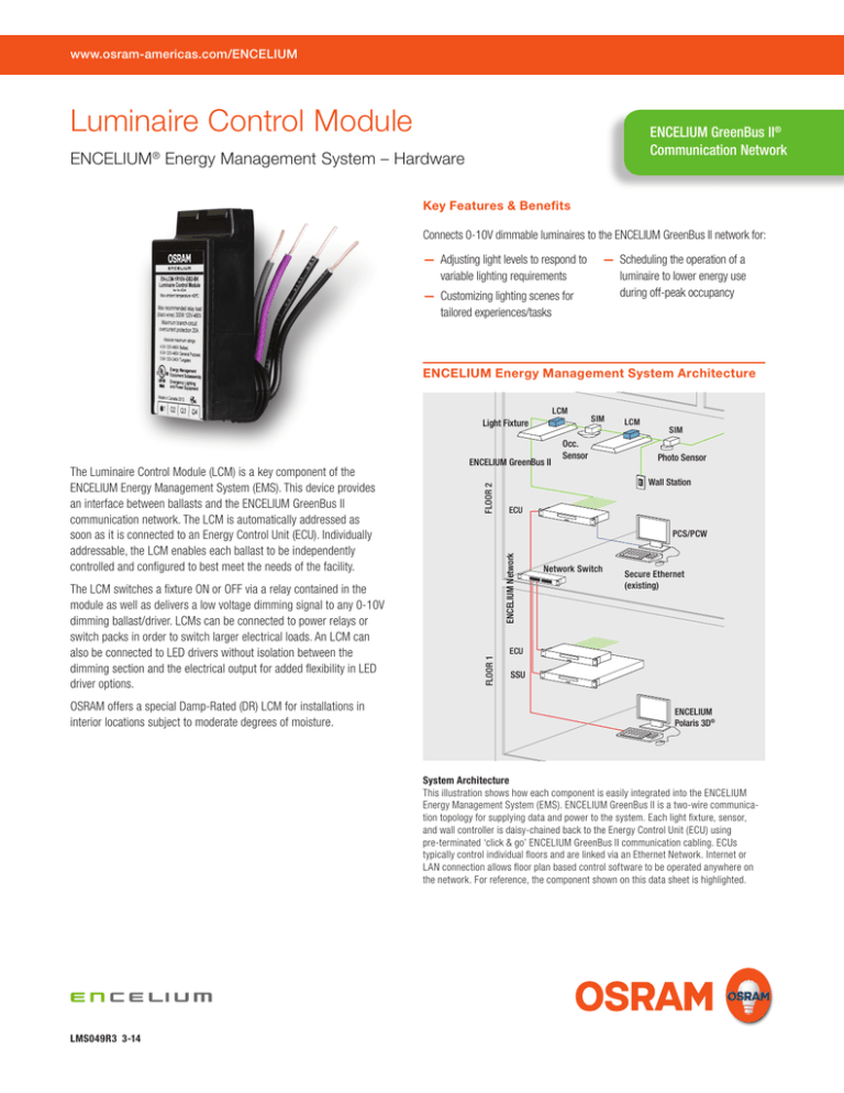
www.osram-americas.com/ENCELIUM Luminaire Control Module ENCELIUM GreenBus II® Communication Network ENCELIUM® Energy Management System – Hardware Key Features & Benefits Connects 0-10V dimmable luminaires to the ENCELIUM GreenBus II network for: —— Adjusting light levels to respond to variable lighting requirements —— Customizing lighting scenes for tailored experiences/tasks —— Scheduling the operation of a luminaire to lower energy use during off-peak occupancy ENCELIUM Energy Management System Architecture LCM Light Fixture OSRAM offers a special Damp-Rated (DR) LCM for installations in interior locations subject to moderate degrees of moisture. FLOOR 2 Occ. Sensor LCM SIM Photo Sensor Wall Station ECU PCS/PCW ENCELIUM Network The LCM switches a fixture ON or OFF via a relay contained in the module as well as delivers a low voltage dimming signal to any 0-10V dimming ballast/driver. LCMs can be connected to power relays or switch packs in order to switch larger electrical loads. An LCM can also be connected to LED drivers without isolation between the dimming section and the electrical output for added flexibility in LED driver options. ENCELIUM GreenBus II FLOOR 1 The Luminaire Control Module (LCM) is a key component of the ENCELIUM Energy Management System (EMS). This device provides an interface between ballasts and the ENCELIUM GreenBus II communication network. The LCM is automatically addressed as soon as it is connected to an Energy Control Unit (ECU). Individually addressable, the LCM enables each ballast to be independently controlled and configured to best meet the needs of the facility. SIM Network Switch Secure Ethernet (existing) ECU SSU ENCELIUM Polaris 3D® System Architecture This illustration shows how each component is easily integrated into the ENCELIUM Energy Management System (EMS). ENCELIUM GreenBus II is a two-wire communication topology for supplying data and power to the system. Each light fixture, sensor, and wall controller is daisy-chained back to the Energy Control Unit (ECU) using pre-terminated ‘click & go’ ENCELIUM GreenBus II communication cabling. ECUs typically control individual floors and are linked via an Ethernet Network. Internet or LAN connection allows floor plan based control software to be operated anywhere on the network. For reference, the component shown on this data sheet is highlighted. LMS049R3 3-14 Ordering Information Item Number 45552 45553 Ordering Description EN-ILCM-1R10V-GB2-BK EN-ILCM-1R10V-GB2-BKDR Field Bus GB2 GB2 Modifiers Black Housing (BK) Black Housing/Damp-Rated (BK/DR) Label Color Orange Orange NAED 45552 & 45553 (with orange labeling) replace NAED 45244 & 45245 (with black labeling) for added flexibility with a range of LED drivers. ENCELIUM ® Luminaire Control Module Power Feed LINE LINE NEUTRAL NEUTRAL Power Feed CK BLA KBLACK C BLA BLACK 1.18" 1.18" (30mm) (30mm) Wire Table Wire Color BLACK BLACK VIOLET GREY BLACK BLACK VIOL VIO GRE GERT LET Y EY BLACK BLACK 2.38 2.38 " " (60.7mm) (60.7mm) 1.2 1.2 "" (30.48mm) (30.48mm) VIOLET VIOLET VIOLET/ VIOLET/ + + GREY GREY GREY/- GREY/ LCM LCM Function Space for Line In/Out –Space Relay forContact ENCELIUM ENCELIUM GreenBus II Line In/Out –GreenBus Relay Contact II connections Class 2, Lowconnections Voltage, 0-10VDC, 25mA max. Class 2, Low Voltage Return/Common Wire Length 12" 12" 36" 36" ® ® ® LCMLCM 0.39" 0.39" (9.91mm) (9.91mm) 0.62" 0.62" (15.7mm) (15.7mm) ® Specifications 0-10V Electronic 0-10V Electronic Ballast/Driver Ballast/Driver —— Dimensions: 1.18" W X 2.38" L X 0.62" H (30mm W X 60.7mm L X 15.7mm H) —— Operating temperature range: -40°C (-40°F) to 55°C (131°F) —— Suitable for luminaire or junction box mounting in standard 1/2" knockout (7/8" dia.) —— Absolute Maximum Ratings (all rated voltages have a tolerance of +/-10%): – 2.5A 120-480 VAC Electronic Ballast – 4.5A 120-480 VAC Ballast – 4.5A 120-480 VAC Resistive – 4.5A 120-480 VAC Tungsten – 4.5A 120-480 VAC General Purpose —— Single 0-10V dimming output (IEC 60929 Annex E). Capable of sinking 25mA (this is equivalent to 10 typical dimming ballasts/drivers) —— FCC Part 15/ICES-003 —— Safety approvals: – Energy Management Equipment (UL 916 cULus Listed) – Emergency Lighting Equipment (UL 924 cULus Listed) – Heat and Smoke Release for Air-Handling Spaces (UL 2043) —— Connects to the ENCELIUM Energy Management System via two ports that accept pre-terminated ENCELIUM GreenBus II® Communication Cable —— Complies with the following electromagnetic requirements: – EN 61000-4-2 – EN 61000-4-4 – EN 61000-4-5 Install in accordance with all applicable national and local electrical and building codes. 1.1 (30 VIOLET GREY (60.7mm) LCM CK BLA K C BLA BLACK BLACK LCM 0.39" (9.91mm) LINE NEUTRAL 0.62" (15.7mm) Power Feed VIOL GRE ET Y VIOLET VIOLET/ + GREY GREY/ - 1.18" (30mm) Wiring Diagram 1.2" 2.38" (30.48mm) (60.7mm) The mechanical construction allows for simple installation of the LCM LCM to an available 1/2 inch knock-out on the side or on top of Space a fixture for ENCELIUM (as shown to the right). ENCELIUM GreenBus II communication wiring GreenBus II connections is still accessible from the outside of the fixture, while all necessary wiring to the electronic dimming ballast is available on the inside. ® 0.39" (9.91mm) 0.62" (15.7mm) For some installations, a junction box may be required. It is recommended to securely mount the LCM to the junction box (as shown to the right) using an available 1/2 inch knock-out and a retainer nut. 100 Endicott Street Danvers, MA 01923 USA Phone1-800-LIGHTBULB www.osram-americas.com OSRAM is a registered trademark of OSRAM GmbH. ENCELIUM, GreenBus II and Polaris 3D are registered trademarks. Specifications subject to change without notice. LCM ® Americas Headquarters LCM LCM 0.39" (9.91mm) 1.18" (30mm) 1.2" (30.48mm) 2.38" (60.7mm) Space for ENCELIUM® GreenBus II® connections 0.62" (15.7mm) 0-10V Electronic Ballast/Driver (30.48mm) GREY/ - Space for ENCELIUM® GreenBus II® connections Dimensions © 2014 OSRAM VIOLET/ + 0-10V Electronic Ballast/Driver
