Quartz Crystal Drive Level
AN-830
APPLICATION NOTE
Introduction
Crystal drive level is the amount of power dissipated in a crystal which is usually specified in microwatts or milliwatts. It can be
calculated by measuring the excitation current flowing through the crystal. The maximum drive level is the most power the crystal
can dissipate while still maintaining operation with all electrical parameters guaranteed. Drive level should be maintained at the
minimum levels necessary to initiate proper start-up and assure steady state oscillation. Some of the larger crystal packages like
HC49 tend to have higher drive level limits while the smaller crystal packages like 5x7mm and 2.5 x 3.2.mm have lower drive
level. To ensure that premature aging or damage to the crystal does not occur, drive level should be considered.
Though drive level is specified in most quartz crystal datasheets, at times it is overlooked. Drive level is an important factor when
designing or evaluating an oscillator circuit.
Measuring Drive Level
There are multiple ways of measuring drive level. Using a current probe is most reliable which is similar to current flowing through
a resistor. Using a FET probe is also common but has disadvantages on an inverter type oscillator, like a Pierce. On an inverter
type oscillator, there is phase difference between the signal at the crystal input and output which make it difficult to accurately
measure the voltage across the crystal. The equations and examples below will show the requirements for measuring drive level
using a current probe.
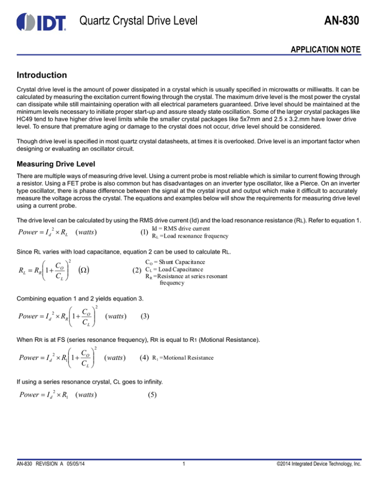
The drive level can be calculated by using the RMS drive current (Id) and the load resonance resistance (RL). Refer to equation 1.
Id = RMS drive current
2
Power I d RL ( watts )
(1) R =Load resonance frequency
L
Since RL varies with load capacitance, equation 2 can be used to calculate RL.
C
RL RR 1 O
CL
2
C O = Shunt Capacitance
(2) CL = Load Capacitance
R R =Resistance at series resonant
frequency
Combining equation 1 and 2 yields equation 3.
C
Power I d RR 1 O
CL
2
2
( watts )
(3)
When RR is at FS (series resonance frequency), RR is equal to R1 (Motional Resistance).
C
Power I d R1 1 O
CL
2
2
( watts )
(4)
R 1 =Motional Resistance
If using a series resonance crystal, CL goes to infinity.
Power I d R1 ( watts )
2
AN-830 REVISION A 05/05/14
(5)
1
©2014 Integrated Device Technology, Inc.
AN-830
Example Calculation
For this example, a Tektronix CT-6 probe was used to measure the drive current. When placing the current probe, special
attention should be given to the orientation. For inverter type oscillators, the drive current should be measured on the output side
of the crystal in order to contain the influence of the oscillator. Refer to Figure 1.
Figure 1. Oscilloscope and current probe connection
Oscilloscopes measure voltage versus time, though the display value is in mV, the current probe converts the electric field to AC
current. The voltage can be ignored; in reality it is current. Oscilloscopes can display AC current in peak, peak to peak, or RMS.
For most cases, we can assume the waveform is a pure sine-wave, hence the equation 6 applies. Refer to equation 6 and Figure
2.
I RMS
I pk
2
I pkpk
2 2
( A)
( 6)
Figure 2. Sample AC Current waveform. IRMS = 1.74mA
QUARTZ CRYSTAL DRIVE LEVEL
2
REVISION A 05/05/14
AN-830
Using a Saunders & Associates 250B Network Analyzer, the relevant crystal parameters can be characterized. For this example,
a 25MHz, HC49 type crystal was used. Refer to Figure 3.
Figure 3. S&A Crystal Parameters, 25MHz
Using equation 3 in combination with IRMS from figure 2 and RL from values in Figure 3 yields the drive level below.
2
C
2.9 pf
Power I d RR 1 O (1.74mA) 2 14 1
18 pf
CL
2
2
57.14uW
The drive level contains variables from both the crystal and oscillator; hence both the crystal type and frequency will affect the
drive level. When characterizing an oscillator, it should be verified across minimum and maximum frequency, CL, and RL. For
the example above, the drive level is 57.14µW for a 25MHz, HC49 crystal on this specific oscillator.
This example yielded 57.14µW of drive level. In order to avoid poor aging or crystal damage, this value should be compared to
the maximum level recommended by the crystal manufacturer.
REVISION A 05/05/14
3
QUARTZ CRYSTAL DRIVE LEVEL
Corporate Headquarters
Sales
Tech Support
6024 Silver Creek Valley Road
San Jose, CA 95138 USA
1-800-345-7015 or 408-284-8200
Fax: 408-284-2775
www.IDT.com
email: clocks@idt.com
DISCLAIMER Integrated Device Technology, Inc. (IDT) and its subsidiaries reserve the right to modify the products and/or specifications described herein at any time and at IDT’s sole discretion. All information in
this document, including descriptions of product features and performance, is subject to change without notice. Performance specifications and the operating parameters of the described products are determined
in the independent state and are not guaranteed to perform the same way when installed in customer products. The information contained herein is provided without representation or warranty of any kind, whether
express or implied, including, but not limited to, the suitability of IDT’s products for any particular purpose, an implied warranty of merchantability, or non-infringement of the intellectual property rights of others. This
document is presented only as a guide and does not convey any license under intellectual property rights of IDT or any third parties.
IDT’s products are not intended for use in applications involving extreme environmental conditions or in life support systems or similar devices where the failure or malfunction of an IDT product can be reasonably
expected to significantly affect the health or safety of users. Anyone using an IDT product in such a manner does so at their own risk, absent an express, written agreement by IDT.
Integrated Device Technology, IDT and the IDT logo are registered trademarks of IDT. Product specification subject to change without notice. Other trademarks and service marks used herein, including protected
names, logos and designs, are the property of IDT or their respective third party owners.
Copyright ©2014 Integrated Device Technology, Inc.. All rights reserved.


