,QIR6KHHW*+66HULHVRI
GHS Series Oil Change System
110725
Installation, Operation, and Maintenance
,QVWDOODWLRQ/RFDWLRQ Choose a location that
is out of the way of engine room traffic.
Most installers select a vertical bulkhead
installation with plumbing to the engine oil
pans at the bottom, but installation in any
orientation is acceptable.
(OHFWULFDO Full voltage is required for
efficient and safe operation. Refer to the wire
size selection chart included and run the
appropriate wire size to the location you have
selected. Remove (4) thumbscrews that
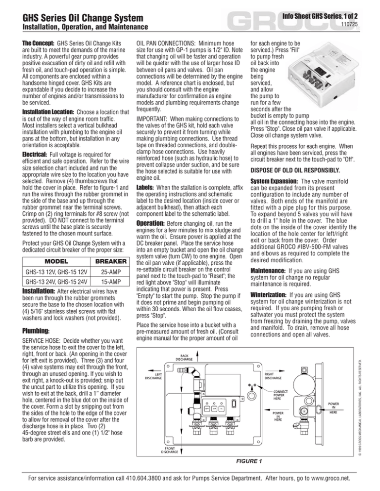
hold the cover in place. Refer to figure-1 and
run the wires through the rubber grommet in
the side of the base and up through the
rubber grommet near the terminal screws.
Crimp on (2) ring terminals for #8 screw (not
provided). DO NOT connect to the terminal
screws until the base plate is securely
fastened to the chosen mount surface.
Protect your GHS Oil Change System with a
dedicated circuit breaker of the proper size:
MODEL
BREAKER
GHS-13 12V, GHS-15 12V
25-AMP
GHS-13 24V, GHS-15 24V
15-AMP
,QVWDOODWLRQ After electrical wires have
been run through the rubber grommets
secure the base to the chosen location with
(4) 5/16" stainless steel screws with flat
washers and lock washers (not provided).
3OXPELQJ
SERVICE HOSE: Decide whether you want
the service hose to exit the cover to the left,
right, front or back. (An opening in the cover
for left exit is provided). Three (3) and four
(4) valve systems may exit through the front,
through an unused opening. If you wish to
exit right, a knock-out is provided; snip out
the uncut part to utilize this opening. If you
wish to exit at the back, drill a 1” diameter
hole, centered in the blue dot on the inside of
the cover. Form a slot by snipping out from
the sides of the hole to the edge of the cover
to allow for removal of the cover after the
discharge hose is in place. Two (2)
45-degree street ells and one (1) 1/2" hose
barb are provided.
OIL PAN CONNECTIONS: Minimum hose
size for use with GP-1 pumps is 1/2" ID. Note
that changing oil will be faster and operation
will be quieter with the use of larger hose ID
between oil pans and valves. Oil pan
connections will be determined by the engine
model. A reference chart is enclosed, but
you should consult with the engine
manufacturer for confirmation as engine
models and plumbing requirements change
frequently.
IMPORTANT: When making connections to
the valves of the GHS kit, hold each valve
securely to prevent it from turning while
making plumbing connections. Use thread
tape on threaded connections, and doubleclamp hose connections. Use heavily
reinforced hose (such as hydraulic hose) to
prevent collapse under suction, and be sure
the hose selected is suitable for use with
engine oil.
/DEHOV When the stallation is complete, affix
the operating instructions and schematic
label to the desired location (inside cover or
adjacent bulkhead), then attach each
component label to the schematic label.
2SHUDWLRQ Before changing oil, run the
engines for a few minutes to mix sludge and
warm the oil. Ensure power is applied at the
DC breaker panel. Place the service hose
into an empty bucket and open the oil change
system valve (turn CW) to one engine. Open
the oil pan valve (if applicable), press the
re-settable circuit breaker on the control
panel next to the touch-pad to "Reset"; the
red light above "Stop" will illuminate
indicating that power is present. Press
"Empty" to start the pump. Stop the pump if
it does not prime and begin pumping oil
within 30 seconds. When the oil flow ceases,
press "Stop".
Place the service hose into a bucket with a
pre-measured amount of fresh oil. (Consult
engine manual for the proper amount of oil
for each engine to be
serviced.) Press "Fill"
to pump fresh
oil back into
the engine
being
serviced,
and allow
the pump to
run for a few
seconds after the
bucket is empty to pump
all oil in the connecting hose into the engine.
Press "Stop". Close oil pan valve if applicable.
Close oil change system valve.
Repeat this process for each engine. When
all engines have been serviced, press the
circuit breaker next to the touch-pad to "Off".
DISPOSE OF OLD OIL RESPONSIBLY.
6\VWHP([SDQVLRQ The valve manifold
can be expanded from its present
configuration to include any number of
valves. Both ends of the manifold are
fitted with a pipe plug for this purpose.
To expand beyond 5 valves you will have
to drill a 1" hole in the cover. The blue
dots on the inside of the cover identify the
location of the hole center for left/right
exit or back from the cover. Order
additional GROCO #IBV-500-FM valves
and elbows as required to complete the
desired modification.
0DLQWHQDQFH If you are using GHS
system for oil change no regular
maintenance is required.
:LQWHUL]DWLRQ If you are using GHS
system for oil change winterization is not
required. If you are pumping fresh or
saltwater you must protect the system
from freezing by draining the pump, valves
and manifold. To drain, remove all hose
connections and open all valves.
9 1999 GROSS MECHANICAL LABORATORIES, INC. ALL RIGHTS RESERVED.
7KH&RQFHSW GHS Series Oil Change Kits
are built to meet the demands of the marine
industry. A powerful gear pump provides
positive evacuation of dirty oil and refill with
fresh oil, and touch-pad operation is simple.
All components are enclosed within a
handsome hinged cover. GHS Kits are
expandable if you decide to increase the
number of engines and/or transmissions to
be serviced.
FIGURE 1
For service assistance/information call 410.604.3800 and ask for Pumps Service Department. After hours, go to www.groco.net.
,QIR6KHHW*+66HULHVRI
GHS Series Oil Change System
110725
Installation, Operation, and Maintenance
3$57
,7(0 180%(5
1
2
3
4
5
6
7
8
9
10
11
12
13
14
15
16
GP-1-C
1032X58HS
10S
10SS
Key-1
GBK-09-0938
GB-09-0938
20L
031-075-8
2-029
GP-1-375
(Volts)-F
GHS Control Asy
M350-3
M350-4
M350-5
M350-6
IBV-500-FM
GHS5-B
GHS5-C
832X12KN
Elbow-3
PTH-3850
Cover
Screw
Washer
Lockwasher
Key
Gear
Gear
Washer
Seal
O-Ring
Pump Housing
Motor
Pedestal
3-Valve Manifold Assy
4-Valve Manifold Assy
5-Valve Manifold Assy
6-Valve Manifold Assy
1/2" Valve (3 shown here)
Base and Cover
Cover and Base
Knurled Screw
3/8" 45-deg Street Ell
3/8" NPT x 1/2" Hose
P-9
Service Kit
6(59,&(
47< .,7
1
6
6
2
1
1
1
1
2
1
1
1
1
1
1
1
1
1
1
1
1
2
1
*
*
*
9 1999 GROSS MECHANICAL LABORATORIES, INC. ALL RIGHTS RESERVED.
17
18
19
3$571$0(
For service assistance/information call 410.604.3800 and ask for Pumps Service Department. After hours, go to www.groco.net.


