JET COOLER (COLD AIR GENERATOR)
advertisement

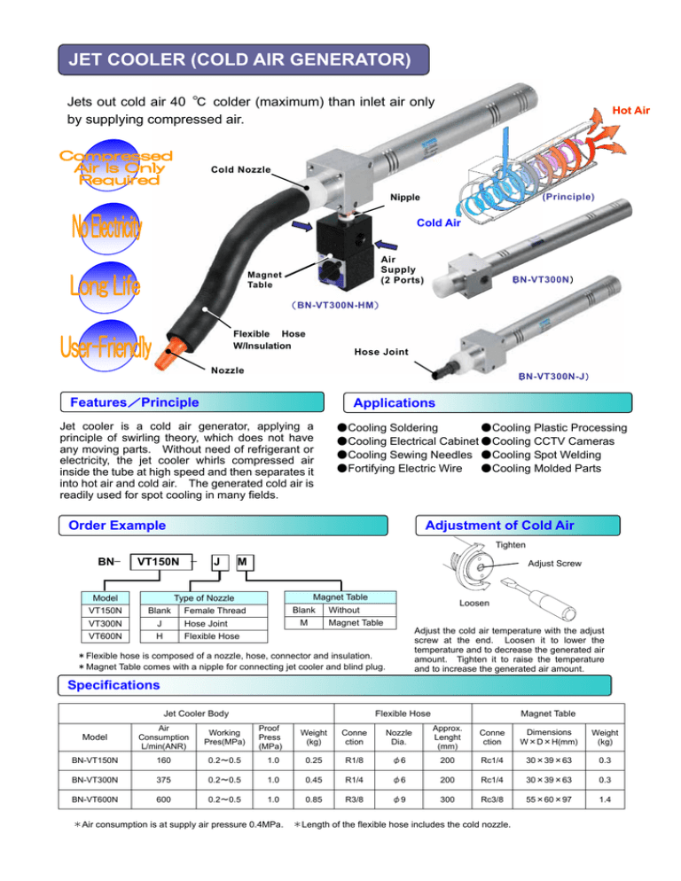
JET COOLER (COLD AIR GENERATOR) Jets out cold air 40 ℃ colder (maximum) than inlet air only by supplying compressed air. Hot Air Cold Nozzle (Principle) Nipple Cold Air Air Supply (2 Ports) Magnet Table (BN-VT300N) (BN-VT300N-HM) Flexible Hose W/Insulation Hose Joint Nozzle (BN-VT300N-J) Features/Principle Applications Jet cooler is a cold air generator, applying a principle of swirling theory, which does not have any moving parts. Without need of refrigerant or electricity, the jet cooler whirls compressed air inside the tube at high speed and then separates it into hot air and cold air. The generated cold air is readily used for spot cooling in many fields. ●Cooling Soldering ●Cooling Plastic Processing ●Cooling Electrical Cabinet ●Cooling CCTV Cameras ●Cooling Sewing Needles ●Cooling Spot Welding ●Fortifying Electric Wire ●Cooling Molded Parts Order Example Adjustment of Cold Air Tighten BN− VT150N − Model VT150N J M Adjust Screw Magnet Table Type of Nozzle Blank Blank Female Thread VT300N J Hose Joint VT600N H Flexible Hose M Loosen Without Magnet Table Adjust the cold air temperature with the adjust screw at the end. Loosen it to lower the temperature and to decrease the generated air amount. Tighten it to raise the temperature and to increase the generated air amount. *Flexible hose is composed of a nozzle, hose, connector and insulation. *Magnet Table comes with a nipple for connecting jet cooler and blind plug. Specifications Jet Cooler Body Model Air Consumption L/min(ANR) Working Pres(MPa) BN-VT150N 160 0.2∼0.5 BN-VT300N 375 BN-VT600N 600 Flexible Hose Proof Press (MPa) Magnet Table Weight (kg) Conne ction Nozzle Dia. Approx. Lenght (mm) 1.0 0.25 R1/8 φ6 200 Rc1/4 30×39×63 0.3 0.2∼0.5 1.0 0.45 R1/4 φ6 200 Rc1/4 30×39×63 0.3 0.2∼0.5 1.0 0.85 R3/8 φ9 300 Rc3/8 55×60×97 1.4 *Air consumption is at supply air pressure 0.4MPa. Conne ction Dimensions W×D×H(mm) Weight (kg) *Length of the flexible hose includes the cold nozzle. Dimensions ● BN-VT150N BN-VT300N BN-VT600N 4-M5 x 0.8 Depth 8 d (Compressed air supply port) 2-φM Temp. adjust screw Hot air exhaust port (mm) D Cold air outlet port Symbol A B C d D E F G I J L M N O BN-VT150N 26 31 5 Rc1/8 Rc1/8 12 26 35 171 25 228 4.5 25 22 BN-VT300N 31 38 5 Rc1/4 Rc1/4 18 33 40 246 30 315 5.5 30 28 BN-VT600N 45 49 6 Rc3/8 Rc3/8 25 40 50 249 38 343 5.5 38 38 Model ● Hose Joint (mm) A L P (Hose Inner Dia.) Q R BN-VT150N-J 26 262 8 10 34 BN-VT300N-J 31 353 10 12 38 BN-VT600N-J 45 384 12 14 41 Symbol Model Supply Air Press 0.5MPa 0.4MPa 0.3MPa 0.2MPa 0 0.5 1 1.5 2 2.5 3 BN-VT600N BN-VT300N 45 40 35 30 25 20 15 10 5 0 Supply Air Press 0.5MPa 0.4MPa 0.3MPa 0.2MPa 0 0.5 ニードル回転数 Adjustment Turns *Temperature Drop: Temperature drop against inlet air. 1 1.5 2 2.5 50 45 40 35 30 25 20 15 10 5 0 Supply Air Press 0.5MPa Temperature 空 気 降 下 温drop 度 ( ℃(℃) ) BN-VT150N 45 40 35 30 25 20 15 10 5 0 Temperature 空 気 降 下 温Drop 度 ( ℃(℃) ) Temperature 空 気 降 下 温Drop 度 ( ℃ (℃) ) Temperature Characteristics 3 0.4MPa 0.3MPa 0.2MPa 0 0.5 1 1.5 *Adjustment Turns: Number of rotating the adjust screw. ・Please make sure that air filters and regulators are equipped with the air line system. ・For use in cold temperature, use an air dryer to prevent freezing. ・For correct handling, read the instruction manual before installing. NIHON SEIKI CO., LTD. ●Head Office/Plant 2-8 Yogikita, Yao City , Osaka 581-0016 Japan TEL. 81-72-923-0481 FAX. 81-72-994-3603 ●Osaka Office 2-8 Yogikita, Yao City , Osaka 581-0016 Japan TEL. 81-72-923-0481 FAX. 81-72-994-3603 ●Tokyo Office 1-16-23 Nakamagome, Ota-ku, Tokyo 140-0027 Japan TEL. 81-3-3777-6111 FAX. 81-3-3777-6116 ●Nagoya Office 3-2-16 Yoshino, Higashi-ku, Nagoya-City, Aichi 485-0039 Japan TEL. 81-52-937-2180 FAX. 81-52-937-2181 URL: http://www.nihonseiki.com 2 2.5 ニードル回転数 Adjustment Turns ニードル回転数 Adjustment Turns ●Agency 3 3.5


