physics 107 lab #1: o`scope and sound
advertisement

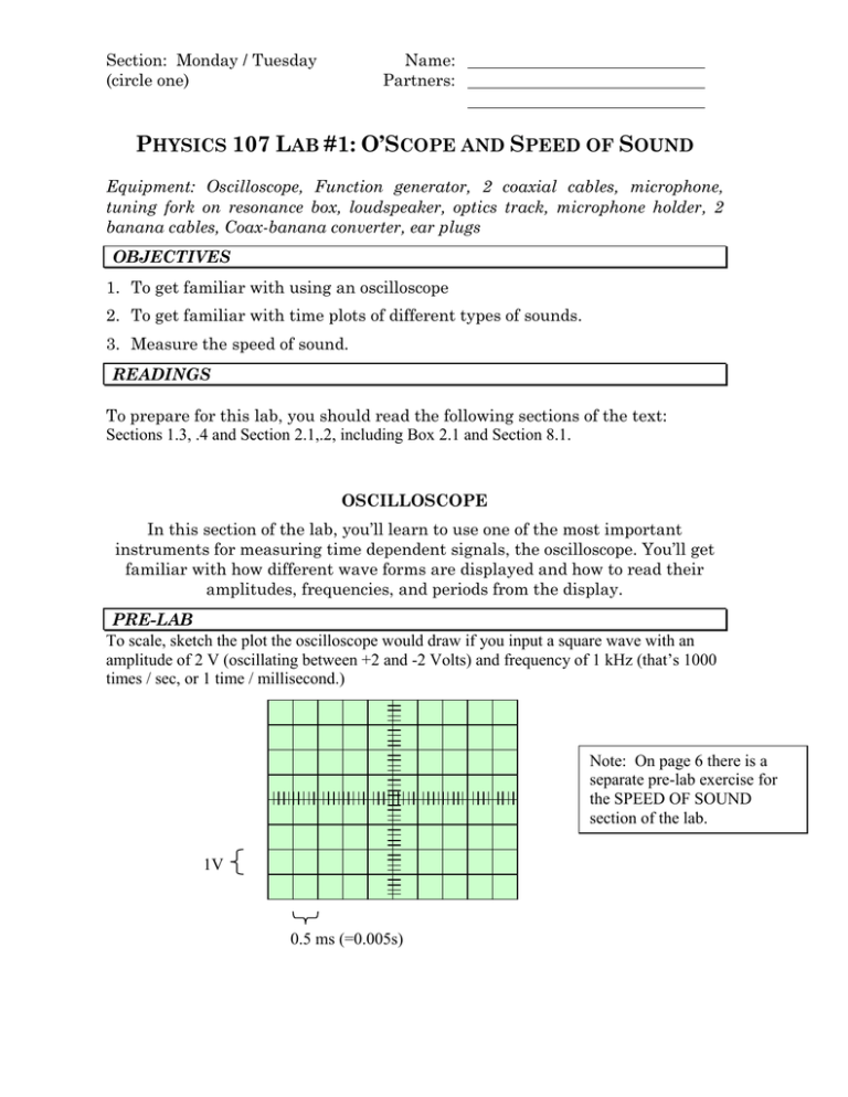
Section: Monday / Tuesday (circle one) Name: Partners: PHYSICS 107 LAB #1: O’SCOPE AND SPEED OF SOUND Equipment: Oscilloscope, Function generator, 2 coaxial cables, microphone, tuning fork on resonance box, loudspeaker, optics track, microphone holder, 2 banana cables, Coax-banana converter, ear plugs OBJECTIVES 1. To get familiar with using an oscilloscope 2. To get familiar with time plots of different types of sounds. 3. Measure the speed of sound. READINGS To prepare for this lab, you should read the following sections of the text: Sections 1.3, .4 and Section 2.1,.2, including Box 2.1 and Section 8.1. OSCILLOSCOPE In this section of the lab, you’ll learn to use one of the most important instruments for measuring time dependent signals, the oscilloscope. You’ll get familiar with how different wave forms are displayed and how to read their amplitudes, frequencies, and periods from the display. PRE-LAB To scale, sketch the plot the oscilloscope would draw if you input a square wave with an amplitude of 2 V (oscillating between +2 and -2 Volts) and frequency of 1 kHz (that’s 1000 times / sec, or 1 time / millisecond.) Note: On page 6 there is a separate pre-lab exercise for the SPEED OF SOUND section of the lab. 1V 0.5 ms (=0.005s) EXPERIMENT Oscilloscope Function Generator RUN/ STOP CH 1 CH 2 Trigger Out (on back) EXT TRIG The following activities are for you to get familiar with the equipment. While these written instructions cover most of it, feel free to call on the instructor with any questions sometimes it’s a lot easier to communicate in person than in wirting. A. Set-up (your instructor should have already done these steps for you, but read through and look to make sure that that’s the case) 1. Connect a BNC – banana converter to the Function Generator’s “Output”, then connect that to the Oscilloscope’s “Channel 2” input via a BNC cable. 2. Connect the Function Generator’s “Trigger” output (on the back) to the Oscilloscope’s external “Trigger” input using another BNC cable. Trigger tells the Oscilloscope when to re-plot its screen. 3. Set the Oscilloscope’s Trigger to “Ext” so it’s ‘watching’ the function generator’s trigger output. 1. Push “Trig Menu” button and a menu will appear to the right of the screen; it’s controlled by the adjacent buttons. 2. If the second box in that menu doesn’t say “Source Ext”, press the button adjacent to it a few times. 4. Set the Oscilloscope to Display just Channel 2 1. Tapping the “Ch 2 Menu” button twice toggles between displaying and not displaying Ch 2; ditto for the “Ch 1 Menu” button. So if Ch 2 is not displayed / if Ch 1 is displayed, tap these menu buttons a couple of times. B. Obtain a Square-wave trace. You’ll try to reproduce the picture you predicted on the previous page. 1. Set the Function Generator to output a 1 kHz square wave with 2 Volt amplitude. To do this… 1. The “waveform” button at the top and near the middle of the Function Generator gives a menu from which to select (by turning the “voltage” dial) the shape of the wave to be produced; a smooth sine wave, a jagged triangle wave, or a blocky square wave – select the square wave and then push the Voltage button. 2. Pushing the Function Generator’s “frequency” button selects between the Hz scale the kHz (1000 Hz) scale; push it to select “kHz.” Page 2 Physics 107 Lab #1: O’scope & Speed of Sound 3. Dial the Frequency value to 1 kHz. Note: the little arrow buttons at the bottom of the Function Generator switch the scale on which you’re adjusting the frequency and voltage when you’re turning those dials. 4. Dial the Voltage value to 2 Volts. 2. Adjust the Oscilloscope to display the square wave that the function generator is producing so it . To do this… 1. Turning the big Channel 2 dial stretches the vertical scale, how many Volts per grid line; the scale will get written on the screen below the plot. Turn the dial until it says “CH2 1.00V” at the bottom of the screen; the trace should be 4 grid boxes tall from bottom to top. 2. Turning the big dial on the right stretches the horizontal scale, how many milliseconds per grid line; again, the scale will get written on the screen below the plot beside a big “M”. Turn this dial until, the timing reads “M 500 s” (500 s = 0.5 ms.) 3. Adjust the O’scope’s horizontal and vertical alignment. To do this… 1. The small dial above Chanel 2 moves the trace up-down; adjust it so the picture is vertically centered on the screen (peaks are two boxes above the mid line and troughs are two boxes below). 2. The small dial above External Trigger moves the trace left-right; adjust it so the picture you see best matches the one you drew on page 1. Compare: At this point, the picture on the O’scope’s screen should look pretty much just like the one you predicted on page 1. If it doesn’t, maybe you’d made a mistake with your prediction (feel free to go back and change it) or something’s not set up right with the o’scope and function generator (feel free to ask the instructor for assistance.) 4. Measure and Record the Amplitude, period, and frequency. To do this… 1. Press the “Measure” button near the top of the O’scope. Now, the right side of the screen should list some measurements like CH2 PkPk, CH2 Period, and CH2 Frequency. You can change what measurement is displayed by pressing the adjacent button. 2. The Amplitude should be half the “pk-pk” (short for “peak to peak”) value written to the right of the screen. Amplitude = ________________ (don’t forget to include units) 3. The frequency should also be written on the screen to the right of the plot; it will be labeled “f”. Frequency = _______________ (don’t forget to include units) 4. The period should also be written on the screen to the right of the plot (or, since it’s the inverse of the frequency, P = 1/f, you can use your calculator to find it) Period = _________________ (again, units) Page 3 Physics 107 Lab #1: O’scope & Speed of Sound Now that you’ve done the basic setup and gone through the process once, you’ll get a little more practice. C. Obtain a sine-wave trace. 1. Set the function generator to output a 100 kHz sine wave (if you need to, look back over the instructions in B.1.) 2. Display the sine wave on the oscilloscope (look back over the instructions in B.2 if you need to.) Note: you’ll definitely want to adjust the time scale on the o’scope (big dial above “Ext Trig”) so you see a nice, simple sine wave; 5.00 s is good. 3. Record the amplitude, period, and frequency. 1. Amplitude = ½ *“pk-pk”______________ 2. Period = _________________ 3. Frequency = ______________ 4. Repeat for a 10 Hz sine wave. 1. Amplitude = ______________ 2. Period = _________________ 3. Frequency = _______________ D. Observe sound waves. 1. Connect the microphone to the Oscilloscope’s Channel 1 input and switch the o’scope to trace channel 1 instead of channel 2. 1. Press the CH 2 Menu button twice and press the CH1 Menu button once; then press the “measure” button again. 2. Change the triggering to be based on the sound. 1. Press the TRIG MENU button and then use the buttons by the screen to change the SOURCE to CH1. 3. Change the display scale. 1. Dial the Ch 1 Voltage/Div so the bottom of the screen reads “CH1 10.00mV” 2. Dial the Sec/Div so the bottom of the screen reads somewhere around “M 2.5ms.” 4. Make sure the scope isn’t showing the raw signal. 1. Press the Acquire button and make sure that “Sample” is selected, then press the Measure button again. Page 4 Physics 107 Lab #1: O’scope & Speed of Sound 5. Whistle into the microphone and sketch the waveform recorded by the oscilloscope (it doesn’t have to be perfect, but get the general character). 1. Important: to freeze an image on the screen, press the “run / stop” button in the upper right corner of the o’scope; pressing it again unfreezes the screen. CH1 ____mV M _____ms Write in the vertical (ms) and horizontal (mV) scales that the o’scope reports. 3. Repeat for other sounds such as singing, coughing, and speaking. (Experiment a little and adjust the Volts/Div and Sec/Div nobs until you can see a reasonable part of the trace.) Label these according to the kinds of sounds (singing, coughing,…) ___________________________ Page 5 ____________________________ Physics 107 Lab #1: O’scope & Speed of Sound 4. Repeat for a tuning fork and determine the frequency of the waveform. Note: for the tuning fork, place the microphone at the mouth of the resonance box. You’ll probably see a very noisy sine wave; while you’re interested in the frequency of that underlying sine wave (not the high frequency noise), if it’s noisy enough the oscilloscope will report the frequency of the noise instead. So, determine the frequency ‘by hand’ – see how many grid boxes a single period plots across, then multiply that by the amount of time represented by each grid box. That gives you the Period. Period = _____________________ms___ Now, since 1/P = f, you can calculate the frequency. Hopefully it’s fairly close to the value etched in the base of the tuning fork. Frequency = ___________________Hz__ Page 6 Physics 107 Lab #1: O’scope & Speed of Sound SPEED OF SOUND In this section of the lab, you will measure the speed of sound by measuring the wavelength of a sinusoidal tone with a known frequency. A speaker will produce a pure tone and a microphone will sense the disturbances in air pressure, i.e., sound, at different distances from the speaker. You will view the electrical signal driving the speaker and that produced by the microphone; these signals behave as does the sound at the speaker and microphone heads. PRE-LAB 1. Let’s say that if the microphone were one wavelength from the speaker, then the electrical signals driving the speaker and produced by the microphone would be in phase, i.e., the maxima and minima of the two signals would line-up as shown below left (the arrows at the left indicate the each signal’s ‘zero’ level; they’ve been vertically offset for our viewing convenience.) Below right, draw the plot you’d expect to see on the oscilloscope if the microphone were 1 ½ wavelength from the speaker; don’t worry about the relative amplitudes of the two signals. Microphone Signal Microphone Signal Speaker Signal Speaker Signal Speaker and microphone 1 wavelength apart Speaker and microphone 1.5 wavelengths apart 2. Why might the wavelengths for sound waves whose frequencies are much lower than 1 kHz be awkward to measure in the lab room? 3. What is the formula for the speed of sound as a function of temperature in Celsius? Page 7 Physics 107 Lab #1: O’scope & Speed of Sound EXPERIMENT Oscilloscope Function Generator RUN/ STOP CH 1 CH 2 Trigger Out (on back) EXT TRIG A. Set-up (your instructor will be happy to help) 1. Speaker & Microphone Positioning 1. Make sure the speaker is upside down (“RCA” logo is upside down), and place a meter stick pointing straight out from its face. Place the microphone stand on the meter stick with the microphone fairly horizontal and facing the speaker. 2. Move the microphone to a few centimeters from the speaker (much closer than illustrated above). 2. Electrical Connections 1. Before plugging in the speaker: Turn the function generator’s voltage all the way down and use the little arrow buttons to move the cursor to after the decimal in the voltage display: 0.00V. 2. Plug the red and black wires into the back of the speaker and the function generator (if not already done.) 3. Oscilloscope Settings 1. If it isn’t already, set the Oscilloscope’s Trigger back to Source: “Ext.” 2. Set the Oscilloscope to display both Ch1 (microphone) and Ch2 (function generator) signals. B. Data Collection You will repeat the following steps for 5 different frequencies.(note: ear plugs are available in case the noise gets annoying.) 1. To start with, set the function generator to about 6 kHz. 2. Adjust the amplitude so the speaker’s tone is audible, but not bothersome (pushing the arrow buttons on the Function Generator allows you to select the scale on which you’re adjusting the voltage). 3. You may need to adjust the Channel 1 and Channel 2 amplitude scales (vertical on the scope screen) and the time scale (horizontal on the screen) so you can see two sinusoidal traces. One represents the electrical impulse driving the speaker head, and therefore, the speaker head’s motion; the other Page 8 Physics 107 Lab #1: O’scope & Speed of Sound 4. 5. 6. 7. 8. represents the electrical impulse produced by the microphone head’s motion, therefore the pushing of air on the microphone head. Move the Microphone toward or away from the Speaker until the electrical signals from the two are in phase (like the first picture in the pre-lab.) Record the frequency, f, and the Microphone’s position, x1 (you can use where the front edge of the stand hits the meter stick), in the table below. Now, move the Microphone toward or away from the Speaker so that the two signals go out of phase and return in phase once again. You have just changed their separation by one wavelength. Record the new Microphone position, x2, and the difference between it and the previous separation, |x1-x2|, i.e. the wavelength, . Dial the function generator to another frequency that is greater than 1 kHz and repeat the data taking process until you’ve filled in the table. f (kHz) x1 (cm) x2 (cm) (cm) v= f × Average the speeds you calculated above (add them up and divide by 5). vave = _______________________ m/s C. Conclusions Compare your experimental value with one calculated based on room temperature. 1. Note the room temperature. T = _________________°C 2. Calculate the speed of sound theorized for this temperature (see the equation you wrote down in the pre-lab.) vsound theory =______________m/s Page 9 Physics 107 Lab #1: O’scope & Speed of Sound 3. The measured value probably won’t be exactly the theoretical value, but they should be fairly close, say, within 10% of each other. Find the % difference between the value theorized and that you measured. vsound .theory vsound . exp eriment % difference = 100% vsound .theory % difference =_____________________% Page 10 Physics 107 Lab #1: O’scope & Speed of Sound


