Venturi-50-Check List-January 2012
advertisement

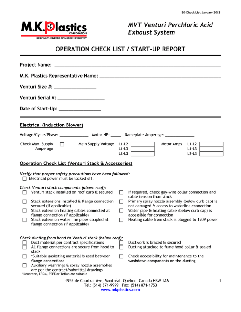
50-Check List-January 2012 MVT Venturi Perchloric Acid Exhaust System OPERATION CHECK LIST / START-UP REPORT Project Name: ___________________________________________________________________ M.K. Plastics Representative Name: _________________________________________________ Venturi Size #: _________________ Venturi Serial #: ___________________ Date of Start-Up: _________________ Electrical (Induction Blower) Voltage/Cycle/Phase: ______________ Motor HP: _____ Nameplate Amperage: ______________ Check Max. Supply Amperage Main Supply Voltage L1-L2 L1-L3 L2-L3 Motor Amps L1-L2 L1-L3 L2-L3 Operation Check List (Venturi Stack & Accessories) Verify that proper safety precautions have been followed: Electrical power must be locked off. Check Venturi stack components (above roof): Venturi stack installed on roof curb & secured Stack extensions installed & flange connection secured (if applicable) Stack extension heating cables connected at flange connection (if applicable) Stack extension water line pipes coupled at flange connection (if applicable) Check ducting from hood to Venturi stack (below roof): Duct material per contract specifications All flange connections are secure from hood to stack *Suitable gasketing material is used between flange connections Auxiliary washrings & spray nozzle assemblies are per the contract/submittal drawings If required, check guy-wire collar connection and cable tension from stack Primary spray nozzle assembly (below curb cap) is not damaged & access to waterline connection Water pipe & heating cable (below curb cap) is accessible for connection Heating cable from stack is plugged to 120V power Ductwork is braced & secured Ducting attached to fume hood collar & sealed Check accessibility for maintenance to the washdown components on the ducting *Neoprene, EPDM, PTFE or Teflon are suitable 4955 de Courtrai Ave, Montréal, Québec, Canada H3W 1A6 Tel: (514) 871-9999 Fax: (514) 871-1753 www.mkplastics.com 1 Check auxiliary washdown components, timer, valves & power (if supplied): Washdown timer installed & electrical wiring Correct sequence of water line valve to per the submittal documents washring/nozzle (refer to submittal documents) Correct power voltage to timer panel, valves, Check water pressure (min. 40 psi) & GPM flow motor starter (refer to submittal documents) rates (refer to submittal documents) Output wiring from timer panel to valves & Verify washdown timer panel PLC, set time & dates motor starter (refer to submittal documents) and verify against submittal questionaire for sequence of operation Water line connections to/from solenoid valves, drainage & to washrings/nozzles Operation Check List (Induction Blower) Verify that proper safety precautions have been followed: Electrical power must be locked off. Check induction blower mechanism components: Duct system complete, connections checked Check for debris in & around fan Check for free movement of fan Bearings are properly lubricated Rotate impeller by hand to verify it has not shifted during transit Check induction blower electrical components: Motor is wired for proper supply voltage All leads are properly grounded Check system accessories: Balancing control damper Duct connection to Venturi stack Check vibration isolators spring tension & clearance Trial “bump”: Turn on power just long enough to start assembly rotating Check drive alignment & tension Run unit up to speed Check Induction Blower hardware: Setscrews attaching wheel hub to shaft (checked for tightness) Setscrews in drive sheaves or coupling (checked for tightness) Nuts holding guards/weather cover (checked for tightness) Bolts in taper-lock bushings (checked for tightness) Fan has been leveled Check fan drain for plug or valve (if supplied) Grounding strap properly grounded (if supplied) Check position of guards/weather cover to prevent rubbing Check access door is secured Motor is properly grounded Wiring checked Fan isolators fastened to fan rails Duct/stack flexible connector Check rotation of the wheel, make sure it is the same as indicated by the arrow marked Rotation Correct any problems which may have been found. Perform check list again until operating properly Nuts on the inlet sleeve (checked for tightness) Nuts & bolts holding the motor (checked for tightness) Grease line connections (if supplied) (checked for tightness) Nuts & bolts holding the fan bearings (checked for tightness) Note: after one week of operation, check all nuts, bolts and setscrews and tighten if necessary. 4955 de Courtrai Ave, Montréal, Québec, Canada H3W 1A6 Tel: (514) 871-9999 Fax: (514) 871-1753 www.mkplastics.com 2 Induction Blower operational checks: Check for excessive vibration Check for unusual noise Check for squealing (improper belt alignment/tension Check vibration isolator movement during operation Check for bearing noise Check if balancing damper blade open & close Note: if a problem is discovered, immediately shut the fan off. Lock out all electrical power and check for the cause of the trouble. Operation Check List (Complete Venturi System) Test run entire system, check for flow & pressure Adjust balancing damper (discharge of blower) if required Check for vibration & excessive noise in ductwork Verify valve operation (a flow sensor on the discharge side of the valve may be required) Blower turns on after a wash or remains off? (Check submittal questionaire for requirement) Initiate a trial washdown (manually or automatically) Verify sequential washdown from top-to-bottom Check for leaks in ducting & around auxiliary washdown components Blower shuts off prior to a wash? Check for leaks in ducting & around auxiliary washdown components and valves Note: if a problem is discovered, immediately shut the fan off. Lock out all electrical power and check for the cause of the trouble. Comments (include problems & repairs): _____________________________________________________________________ _____________________________________________________________________ _____________________________________________________________________ _____________________________________________________________________ _____________________________________________________________________ _____________________________________________________________________ _____________________________________________________________________ _____________________________________________________________________ Please indicate the name of ‘party’ who will be responsible for equipment maintenance from this point forward: _________________________________________________________________________________ I have clearly communicated the maintenance requirements to that ‘party’: Technician Signature: ____________________________ Date: ________________ 4955 de Courtrai Ave, Montréal, Québec, Canada H3W 1A6 Tel: (514) 871-9999 Fax: (514) 871-1753 www.mkplastics.com 3


