MIL-C-83522/16B w/AMENDMENT 1 17 AUGUST 2004
advertisement

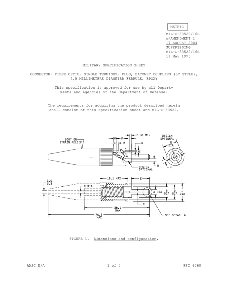
METRIC MIL-C-83522/16B w/AMENDMENT 1 17 AUGUST 2004 SUPERSEDING MIL-C-83522/16B 11 May 1995 MILITARY SPECIFICATION SHEET CONNECTOR, FIBER OPTIC, SINGLE TERMINUS, PLUG, BAYONET COUPLING (ST STYLE), 2.5 MILLIMETERS DIAMETER FERRULE, EPOXY This specification is approved for use by all Departments and Agencies of the Department of Defense. The requirements for acquiring the product described herein shall consist of this specification sheet and MIL-C-83522. FIGURE 1. AMSC N/A Dimensions and configuration. 1 of 7 FSC 6060 MIL-C-83522/16B w/AMENDMENT 1 MM 0.32 2.0 3.3 19.1 38.1 76.2 FIGURE 1. Inches 0.0126 0.08 0.13 0.75 1.50 3.00 Dimensions and configuration - Continued. 2 MIL-C-83522/16B w/AMENDMENT 1 Millimeters Inches Letter Notes Min Max Min Max 2.4985 2.4995 0.09837 0.09841 3 2.498 2.500 0.0983 0.0984 3 B 5.25 5.38 0.207 0.212 C 0.91 1.07 0.036 0.042 D 7.06 min E 7.75 8.00 0.305 0.315 F 2.56 4.50 0.101 0.177 G 0.58 0.89 0.023 0.035 H 1.60 min J 9.40 9.80 0.370 0.386 L 2.00 2.00 0.079 0.079 M 0.64 1.12 0.025 0.044 N 8.56 min Q 1.04 1.60 0.041 0.063 R (SM/MM) 8 25 0.3 1.0 A (SM/MM) A (MM) 0.278 min 0.063 min 0.337 min 4 5 0.3 min 6 R (MM) 8 min 6 X (SM/MM) 0.020 0.063 0.0008 0.0025 7 X (MM) 0.000 0.063 0.0000 0.0025 7 NOTES: 1. Dimensions are in millimeters. 2. Inch equivalents are given for general information only. 3. Use A (SM/MM) for single mode applications. Use A (SM/MM) or A (MM) for multimode applications. 4. L dimension is the diameter of a circle on the surface of the ferrule that is concentric with the axis of the ferrule. 5. Design optional. 6. R dimension is for reference or conceptual design considerations only. This dimension is the radius of the end of the ferrule when the surface of the ferrule is spherical, and L is as given. 7. X dimension is the distance that the apex of the end of the ferrule extends beyond the circle described in note 4. 8. α angle to be between 20° and 35°. FIGURE 1. Dimensions and configuration - Continued. 3 MIL-C-83522/16B w/AMENDMENT 1 REQUIREMENTS: Metals: The plug housing and other metal components shall be of corrosion resistant steel in accordance with SAE AMS-QQ-S-763,ASTM A-276, designation S31803, or nickel-plated brass, alloy 345 or 360, in accordance with ASTM B16. Ferrule material: Ceramic (zirconia). The dust cover, strain relief boot, and protective cap shall be made of thermoplastic or fluorosilicone. Epoxies: Use an epoxy approved by the qualifying activity. Dimensions and configuration: See figure 1. Fiber optic cable requirements: Cable configuration: In accordance with MIL-PRF-85045. Fiber diameter: 50/125 µm, 62.5/125 µm, and 100/140 µm, with the following respective tolerances: 125 ±2 µm (MM), 125 ±1 µm (SM/MM), 140 ± 2µm (MM). Fiber optic contact: Method optical alignment: Lens configuration: Sleeve/ferrule. Not applicable. Coating requirements: Not applicable. Nuclear radiation resistance: Weight: Not applicable. 20 grams maximum. Polarization: Key/slot. Safety wire holes: Not required. Force to engage and disengage: Longitudinal force: Torque: Lubricants: Not applicable. Not applicable. Not applicable. 4 MIL-C-83522/16B w/AMENDMENT 1 Water submersion: Not applicable. Coupling proof torque: Not applicable. Coupling mechanism retention force: Not applicable. Tensile loading: The load shall be 230 newtons minimum and shall not result in any physical damage. Optical properties shall be monitored before and after load. The load shall not be applied to the coupling mechanism. Optical transmittance measurements are not required during the test for the non-locking connectors. Dust (fine sand): Applicable. Perform as specified in the requirements of MIL-C-83522D with the following modifications: a. The connectors shall not be rotated during steps 1 and 3. Each connector shall be oriented in the chamber such that the key slot is in line with the oncoming air flow. The connectors shall be affixed in such a manner that the orientation of the connector does not change throughout the duration of the test. b. The change in optical transmittance shall be measured before the dust test, during the 6 hour exposure period of step 1, before step 3, during the 6 hour exposure period of step 3, and after the test. Samples shall be visually examined, after cleaning, at the conclusion of the dust test. Ozone exposure: Not applicable. High impact shock: Applicable to single mode and multimode locking and nonlocking connectors. Fluid immersion: Not applicable. Residual magnetism: Not applicable. Shock: For SM/MM connectors assembled on single-mode fiber, signal discontinuity is not applicable during shock. For MM connectors and SM/MM connectors assembled on multimode fiber, signal discontinuity is applicable during shock. Plug accessories: Each plug shall be packaged with a minimum of one crimp ferrule, one dust cover, and one strain relief boot. 5 MIL-C-83522/16B w/AMENDMENT 1 Protective cover: The protective cover shall consist of a lanyard which attaches to the optical fiber cable and a cap for covering the connector. The protective cover shall be installable after the connector termination process is complete. The protective cover shall be subjected only to the temperature/humidity cycling and fungus tests. The protective cover shall not be provided with the plug connector, and may be procured separately. Crimp sleeve: The crimp sleeve shall accept single fiber cordage with a maximum outer diameter of 2.50 mm (.098 inch). The plug connector shall meet all requirements when the crimp sleeve is assembled to the plug connector using one of the following: A hex crimp die measuring 4.84 mm ±.05 mm (.190 inch ±.001 inch) across the flats, a circular indent ring crimp die with a 2.67 mm ±.08 mm (.105 inch ±.003 inch) minor diameter and a 3.43 mm ±.008 mm (.135 inch ±.003 inch) major diameter, or a circular indent ring crimp die with a 2.29 mm ±.08 mm (.090 inch ±.003 inch) minor diameter and a 3.05 mm ±.008 mm (.120 inch ±.003 inch) major diameter. Group A inspection: During group verified on all items. All other basis. Weight may be verified on shall be notified of all failures A inspections, plug dimension E shall be dimensions may be verified on a sampled a sampled basis. The qualifying activity during any sampled inspections. The plug connector mates with MIL-C-83522/17 adapter and MIL-C-83522/18 PC mount receptacle. Part or Identifying Number (PIN) is a new term encompassing previous terms used in specifications such as part number, type designator, or identification number and is as follows: M83522/16 - X X X X Configuration Temperature Fiber size Additional considerations Patent notice: Configuration: A (locking boot, long cap) D (nonlocking boot, either long or short cap) E (protective cover) Temperature: H (high) N (normal) Fiber size: X (type I) (125 µm, MM) Y (type II) (125 µm, SM/MM) Z (type I) (140 µm, MM) Additional consideration: S qualified to space flight requirements Deleted. 6 MIL-C-83522/16B w/AMENDMENT 1 Referenced documents. In addition to MIL-C-83522, this specification sheet references the following documents: MIL-C-83522 MIL-C-83522/17 MIL-C-83522/18 MIL-PRF-85045 SAE AMS-QQ-S-763, ASTM A-276 ASTM B-16 The margins of this specification are marked with vertical lines to indicate modifications generated by this amendment. This was done as a convenience only and the Government assumes no liability whatsoever for any inaccuracies in these notoations. Bidders and contractors are cautioned to evaluate the requirements of this document based on the entire content irrespective of the marginal notations. CONCLUDING MATERIAL Custodians: Army - CR Navy - SH Air Force - 11 NASA - NA DLA - CC Preparing activity: DLA- CC (Project 6060-0154) Review activity: Navy - AS Air Force - 13, 19, 93, 99 DIA - DI 7
