70052-0253-00
11/2008
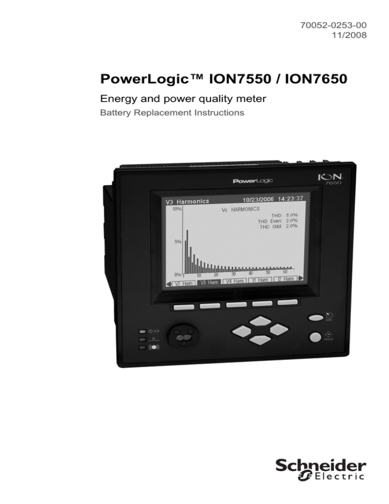
PowerLogic™ ION7550 / ION7650
Energy and power quality meter
Battery Replacement Instructions
PowerLogic ION7550 / ION7650 Battery Replacement Instructions
Hazard Categories and Special Symbols
Read these instructions carefully and look at the equipment to become
familiar with the device before trying to install, operate, service or maintain
it. The following special messages may appear throughout this manual or on
the equipment to warn of potential hazards or to call attention to information
that clarifies or simplifies a procedure.
The addition of either symbol to a “Danger” or “Warning” safety label
indicates that an electrical hazard exists which will result in personal injury if
the instructions are not followed.
This is the safety alert symbol. It is used to alert you to potential personal
injury hazards. Obey all safety messages that follow this symbol to avoid
possible injury or death.
DANGER
DANGER indicates an imminently hazardous situation which, if not avoided, will
result in death or serious injury.
WARNING
WARNING indicates a potentially hazardous situation which, if not avoided, can
result in death or serious injury.
CAUTION
CAUTION indicates a potentially hazardous situation which, if not avoided, can
result in minor or moderate injury.
CAUTION
CAUTION used without the safety alert symbol, indicates a potentially hazardous
situation which, if not avoided, can result in property damage.
Provides additional information to clarify or simplify a procedure.
PLEASE NOTE
Electrical equipment should be installed, operated, serviced and maintained
only by qualified personnel. No responsibility is assumed by Schneider
Electric for any consequences arising out of the use of this material.
© 2008 Schneider Electric. All rights reserved.
3
PowerLogic ION7550 / ION7650 Battery Replacement Instructions
FCC Notice
This equipment has been tested and found to comply with the limits for a Class A digital device, pursuant to Part 15
of the FCC Rules. These limits are designed to provide reasonable protection against harmful interference when the
equipment is operated in a commercial environment.
This equipment generates, uses, and can radiate radio frequency energy and, if not installed and used in accordance
with the instruction manual, may cause harmful interference to radio communications. Operation of this equipment
in a residential area is likely to cause harmful interference in which case the user will be required to correct the
interference at his own expense.
The Ringer Equivalence Number (REN) for the ION7550 / ION7650 optional internal modem is 0.6. Connection to
the ION7550 / ION7650 internal modem should be made via an FCC Part 68 compliant telephone cord (not
supplied). The ION7550 / ION7650 cannot be used on a public coin phone service or party line services.
Network Compatibility Notice for the Internal Modem
The internal modem in meters equipped with this option is compatible with the telephone systems of most countries
in the world. Use in some countries may require modification of the internal modem’s initialization strings. If problems
using the modem on your phone system occur, please contact Schneider Electric Technical Support.
Standards Compliance
CSA: Certified to CAN/ Certified to
CSA C22.2 No.1010-1 UL 3111
Made by Power Measurement Ltd.
Covered by one or more of the following patents:
U.S. Patent No's 7010438, 7006934, 6990395, 6988182, 6988025, 6983211, 6961641, 6957158, 6944555,
6871150, 6853978, 6825776, 6813571, 6798191, 6798190, 6792364, 6792337, 6751562, 6745138,
6737855, 6694270, 6687627, 6671654, 6671635, 6615147, 6611922, 6611773, 6563697, 6493644,
6397155, 6236949, 6186842, 6185508, 6000034, 5995911, 5828576, 5736847, 5650936, D505087,
D459259, D458863, D443541, D439535, D435471, D432934, D429655, D427533.
4
© 2008 Schneider Electric. All rights reserved.
PowerLogic ION7550 / ION7650 Battery Replacement Instructions
Contents
Introduction . . . . . . . . . . . . . . . . . . . . . . . . . . . . . . . 6
Before You Begin . . . . . . . . . . . . . . . . . . . . . . . . . . . 8
Step 1: Removing the Comm Card . . . . . . . . . . . . . 10
Step 2: Removing the I/O Card (or faceplate) . . . . . 11
Step 3: Removing the jumper (if applicable) . . . . . . 12
Step 4: Replacing the battery . . . . . . . . . . . . . . . . . 13
Step 5: Re-installing the Comm Card . . . . . . . . . . . . 13
Step 6: Re-installing the I/O card (or faceplate) . . . . 14
Step 7: Re-powering the meter . . . . . . . . . . . . . . . . 14
Step 8: Resetting the meter clock . . . . . . . . . . . . . . 14
© 2008 Schneider Electric. All rights reserved.
5
PowerLogic ION7550 / ION7650 Battery Replacement Instructions
Introduction
PowerLogic ION7550 / ION7650 meters come equipped with a permanently
installed battery that maintains the meter’s real time clock and non-volatile
memory (NVRAM) during the absence of power to the meter.
In the event the meter’s factory-installed battery discharges, an additional
auxiliary battery can be installed on the meter’s communications card
(Comm Card). Once the new battery is in place, the old battery is
disconnected by removing a jumper on the meter’s main board.
Symptoms of a Discharged Battery
Meter clock loses time or changes to a random time/date
Meter logs 461, 451, 450, or 600 events
CAUTION
RISK OF DATA LOSS
When the auxiliary battery is in use, removing the communications card from the
meter can cause up to 10 minutes worth of time and data loss.
• Ensure all important data from the meter has been retrieved before removing the
communications card.
Failure to follow these instructions can result in permanent data loss.
Battery Specifications
Type
Nominal Capacity
Rated Voltage
Manufacturer
Model Number
AA size lithium LiSOCl2
2.4 Ah
3.6 V
Saft
LS14500
NOTE
The replacement battery must be the exact model number for proper meter
operation and to meet CSA product safety requirements. Purchasing the
battery directly from Schneider Electric ensures the correct battery is used. A
typical AA battery suitable for household electronics will not work in the
meter.
6
© 2008 Schneider Electric. All rights reserved.
PowerLogic ION7550 / ION7650 Battery Replacement Instructions
WARNING
HAZARD OF FIRE, EXPLOSION OR CORROSIVE FUMES
Exposing any lithium battery to heat can cause electrolyte decomposition, flammable or corrosive fume venting, or battery explosion.
• Do not heat the battery above 100°C (212°F) or incinerate it.
• Dispose of the battery according to local regulations.
Failure to follow these instructions can result in death or serious injury.
NOTE: Materials safety data sheets (MSDS) are available from the battery
manufacturer or Schneider Electric.
© 2008 Schneider Electric. All rights reserved.
7
PowerLogic ION7550 / ION7650 Battery Replacement Instructions
Before You Begin
DANGER
HAZARD OF ELECTRIC SHOCK, EXPLOSION OR ARC FLASH
• Apply appropriate personal protective equipment (PPE) and follow safe electrical
work practises such as NFPA 70E.
• This equipment must only be installed and serviced by qualified, licensed
electrical personnel.
• Equipment mounting and installation must conform to all applicable local
electrical codes.
• Install meter bypass switches, PTs, CTs and shorting blocks to conform to all
applicable local electrical codes.
• Never short the secondary of a PT.
• Never open circuit a CT; use the shorting block to short circuit the leads of the CT
before removing the connection to the power meter.
• Never operate a CT with an open secondary.
• Turn off all power supplying this equipment before working on or inside
equipment.
• Always use a properly rated voltage sensing device to confirm power is off.
• Replace all devices, doors and covers before turning on power to this equipment.
• The successful operation of this equipment depends upon proper handling,
installation, and operation. Neglecting fundamental installation requirements
may lead to personal injury as well as damage to electrical equipment or other
property.
Failure to follow these instructions will result in death or serious injury.
Before performing any service on the meter:
Familiarize yourself with the steps in this guide.
Complete the following steps before attempting any retrofits:
8
1.
Wear an anti-static wrist strap.
2.
Ensure all important data from the meter (for example, revenue values)
has been retrieved.
3.
Turn off ALL power to the meter, including high voltage digital inputs and
relay connections.
4.
Use a properly rated voltage sensing device to confirm power is OFF.
5.
Open all PT fuses (or direct voltage input fuses).
6.
Close all CT shorting blocks.
7.
Ensure that all cables still connected to the meter are NOT live.
© 2008 Schneider Electric. All rights reserved.
PowerLogic ION7550 / ION7650 Battery Replacement Instructions
CAUTION
RISK OF DAMAGE TO METER
Components inside the meter are extremely sensitive to electrostatic discharge.
• Wear an anti-static wrist strap at all times when working inside the unit.
Failure to follow these instructions can result in damage to the meter and will
void the meter’s warranty.
Your kit contains:
One lithium replacement battery
One zap strap (cable tie)
Recommended Tools
Phillips #1 screwdriver
Small adjustable wrench
Precision flat-head screwdriver (for captured-wire connectors)
Small slot screwdriver
Needle-nose pliers
Anti-static wrist strap
© 2008 Schneider Electric. All rights reserved.
9
PowerLogic ION7550 / ION7650 Battery Replacement Instructions
Step 1: Removing the Comm Card
1.
Disconnect all wires connected to the Comm Card. Labelling the wires
with tape can help when re-connecting them.
2.
Remove the two screws and lockwashers from the Comm Card at the
back of the meter, using a Phillips #1 screwdriver (see arrows below).
Remove the ground nut, using a small adjustable wrench.
Ground
Nut
3.
Remove the Comm Card by grasping it on the sides of its backplate (see
below) and carefully pulling it out of the socket, away from the chassis.
If the card sticks in the meter, wedge the tip of a flathead screwdriver
between the card’s backplate and the meter chassis and gently pry the
card loose.
10
© 2008 Schneider Electric. All rights reserved.
PowerLogic ION7550 / ION7650 Battery Replacement Instructions
Step 2: Removing the I/O Card (or faceplate)
NOTE
If the meter does not have an I/O Card installed, remove the blank faceplate
on the back of the meter instead. Remove the two screws and lockwashers that
attach the faceplate, using a Phillips #1 screwdriver.
1.
Disconnect all wires connected to the I/O Card. Labelling the wires with
tape can help when re-connecting them.
2.
Remove the two screws and lockwashers from the I/O Card at the back
of the meter, using a Phillips #1 screwdriver (see arrows below).
3.
Remove the I/O Card by grasping it on the sides of its backplate (see
below) and carefully pulling it out of the socket, away from the chassis.
If the card sticks in the meter, wedge the tip of a flathead screwdriver
between the card’s backplate and the meter chassis, and gently pry the
card loose.
© 2008 Schneider Electric. All rights reserved.
11
PowerLogic ION7550 / ION7650 Battery Replacement Instructions
Step 3: Removing the jumper (if applicable)
NOTE
This step only applies if the meter is still using the factory-installed main
board battery and you have never inserted a battery on the meter’s Comm
Card. Removing this jumper disables the main board battery.
12
1.
Using needle-nose pliers, carefully pull the jumper off the header
connector on the main board, next to the CPU (see arrow below). With
the Comm and I/O Cards removed, you can access the header and
jumper via the opening in the back the meter.
2.
Discard the jumper after removal. It is not necessary to remove the main
board battery.
© 2008 Schneider Electric. All rights reserved.
PowerLogic ION7550 / ION7650 Battery Replacement Instructions
Step 4: Replacing the battery
1.
Replace the battery as follows, depending on your situation:
Insert the new battery into the holder on the new Comm Card.
OR
Remove the existing battery from the Comm Card and insert the new
one.
Ensure the battery’s + and – terminals are correctly aligned in the holder.
2.
Secure the battery with the zap strap, as shown below. Trim off excess
strap material.
50-pin CHAMP
connector
1x2 receptacle
connector
zap strap
battery holder
Step 5: Re-installing the Comm Card
1.
Insert the Comm Card by sliding the edges of the circuit board down the
slots along each side of the chassis.
2.
Align the CHAMP connector with the socket and press the card firmly into
place. The socket and the connector are polarized, so the pins in the
connector will not fit into the socket if the card is not oriented correctly.
3.
Ensure the header connector on the main board fits securely into the
receptacle connector on the Comm Card.
The Comm Card is securely inserted into the socket when the backplate
of the card meets the chassis of the meter.
4.
Secure the card with the two screws, lockwashers and the ground nut.
They must be tightened firmly to preserve transient immunity. Ensure the
ground wire is connected to the meter protective ground terminal (for
example, ground nut/lug/post etc.).
5.
Re-connect the wires to the Comm Card as required. See the Installation
Guide for more details.
© 2008 Schneider Electric. All rights reserved.
13
PowerLogic ION7550 / ION7650 Battery Replacement Instructions
Step 6: Re-installing the I/O card (or faceplate)
NOTE
If the meter does not have an I/O Card installed, install the blank faceplate
on the back of the meter instead. Replace the two screws and lockwashers that
attach the faceplate, using a Phillips #1 screwdriver.
1.
Insert the I/O Card by sliding the edges of the circuit board down the
slots along each side of the chassis.
2.
Align the connector with the socket and press the card firmly into place.
The socket and the connector are polarized, so the pins in the connector
will not fit into the socket if the card is not oriented correctly. The I/O Card
is securely inserted into the socket when the backplate of the card meets
the chassis of the meter
3.
Replace the two screws and lockwashers. They must be tightened firmly
to preserve transient immunity.
4.
Re-connect the wires to the I/O Card as required. See the Installation
Guide for more details.
Step 7: Re-powering the meter
NOTE
The meter protective ground terminal must be connected to ground (earth)
before any power is applied to the meter terminals.
1.
Close the PT fuses (or direct voltage input fuses) and open the CT
shorting blocks.
2.
Turn on power to the meter and verify the correct operation of the unit.
Step 8: Resetting the meter clock
Replacing the battery will cause the meter clock to lose time. Be sure to reset
the meter to the correct time and date after re-powering. This can be done
via the front panel’s Time Setup menu or using ION software.
14
© 2008 Schneider Electric. All rights reserved.
PowerLogic ION7550 / ION7650
with WebMeterTM and MeterM@ilTM
Battery Replacement Instructions
For further assistance
please contact us at:
Schneider Electric
Power Monitoring and Control
2195 Keating Cross Road
Saanichton, BC
Canada V8M 2A5
Tel: 1-250-652-7100
295 Tech Park Drive, Suite 100
Lavergne, TN 37086
USA
Tel: 1-615-287-3400
Electropole (38 EQI)
31, rue Pierre Mendès France
F - 38050 Grenoble Cédex 9
Tel : + 33 (0) 4 76 57 60 60
Getting technical support:
Contact your local Schneider Electric sales
representative for assistance or go to the
www.powerlogic.com website.
PowerLogic, ION, ION Enterprise, MeterM@il, WebMeter
and Modbus are are either trademarks or registered
trademarks of Schneider Electric in France, the USA and
other countries. All other trademarks are property of their
respective owners.
Electrical equipment should be installed, operated,
serviced, and maintained only by qualified personnel.
No responsibility is assumed by Schneider Electric for any
consequences arising out of the use of this material.
70052-0253-00
© 2008 Schneider Electric. All rights reserved.
11/2008


