Low Profile Surface Mount Common Mode Chokes
advertisement

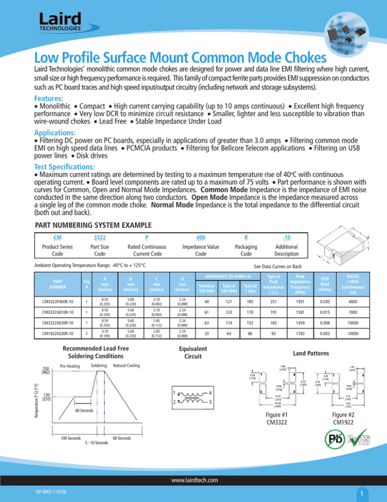
Low Profile Surface Mount Common Mode Chokes Laird Technologies’ monolithic common mode chokes are designed for power and data line EMI filtering where high current, small size or high frequency performance is required. This family of compact ferrite parts provides EMI suppression on conductors such as PC board traces and high speed input/output circuitry (including network and storage subsystems). Features: • Monolithic • Compact • High current carrying capability (up to 10 amps continuous) • Excellent high frequency performance • Very low DCR to minimize circuit resistance • Smaller, lighter and less susceptible to vibration than wire-wound chokes • Lead Free • Stable Impedance Under Load Applications: • Filtering DC power on PC boards, especially in applications of greater than 3.0 amps • Filtering common mode EMI on high speed data lines • PCMCIA products • Filtering for Bellcore Telecom applications • Filtering on USB power lines • Disk drives Test Specifications: • Maximum current ratings are determined by testing to a maximum temperature rise of 40oC with continuous operating current. • Board level components are rated up to a maximum of 75 volts • Part performance is shown with curves for Common, Open and Normal Mode Impedances. Common Mode Impedance is the impedance of EMI noise conducted in the same direction along two conductors. Open Mode Impedance is the impedance measured across a single leg of the common mode choke. Normal Mode Impedance is the total impedance to the differential circuit (both out and back). PART NUMBERING SYSTEM EXAMPLE CM 3322 P 400 R -10 Product Series Code Part Size Code Rated Continuous Current Code Impedance Value Code Packaging Code Additional Description Ambient Operating Temperature Range: -40°C to + 125°C See Data Curves on Back Typical 1 GHz Typical Peak Impedance (W) Peak Impedance Frequency (MHz) DCR MAX (Ohms) RATED I MAX (continuous) mA 121 185 251 1931 0.030 4000 61 123 170 191 1581 0.015 7000 2.24 (0.088) 63 114 152 165 1459 0.008 10000 2.24 (0.088) 33 64 86 93 1783 0.003 10000 Fig # A mm (inches) B mm (inches) C mm (inches) D mm (inches) Nominal 100 MHz Typical 500 MHz CM3322P400R-10 1 8.50 (0.335) 5.60 (0.220) 2.10 (0.083) 2.24 (0.088) 40 CM3322U610R-10 1 8.50 (0.335) 5.60 (0.220) 2.10 (0.083) 2.24 (0.088) CM3322X630R-10 1 8.50 (0.335) 5.60 (0.220) 2.85 (0.112) 2 4.70 (0.185) 5.60 (0.220) 2.85 (0.112) CM1922X330R-10 Recommended Lead Free Soldering Conditions 250 [482] Temperature (º C) [º F] IMPEDANCE (Z) OHMS @ PART NUMBER Pre-Heating Soldering Equivalent Circuit Land Patterns Natural Cooling .88 [.074] 2.92 [.5] 130 [255] 1 4 2 3 60 Seconds 100 Seconds 5 - 10 Seconds 2 .9 [.075] 4 0.46 [.08] 6.53 [.257] 0.26 [.404] Figure #1 CM3322 6.27 [.247] 3 6.35 [.250] 2.95 [.6] 2 4 0.46 [.08] 3 2.72 [.07] 6.53 [.257] Figure #2 CM1922 60 Seconds www.lairdtech.com SIP-BRO-7-0208 Common Mode Bead Impedance CM1922X330R-10 180 Normal 80 120 100 Open 80 Common 60 70 Impedance (Ω) Impedance (Ω) 140 60 40 20 10 10 100 Frequency (MHz) 0 10000 1000 CM3322P400R-10 450 10 1 100 Frequency (MHz) 3000 1000 CM3322P400R-10 300 Z Normal 400 250 350 300 Impedance (Ω) Impedance (Ω) XL 30 20 1 R 50 40 Open 250 200 Common 150 200 R 150 100 100 XL 50 50 0 Z 90 160 0 CM1922X330R-10 100 1 10 100 Frequency (MHz) CM3322U610R-10 350 0 10000 1000 1 Normal 100 Z 200 Impedance (Ω) Impedance (Ω) 250 200 Open 150 100 1 10 100 Frequency (MHz) 10 CM3322X630R-10 180 100 Frequency (MHz) Z R 140 Impedance (Ω) 200 Open 150 100 120 100 Common 80 60 40 50 XL 20 1 10 100 Frequency (MHz) 1000 3000 1000 160 Normal 250 Impedance (Ω) 01 10000 1000 CM3322X630R-10 300 0 XL 50 50 0 R 150 Common 100 3000 1000 Frequency (MHz) CM3322U610R-10 250 300 10 10000 0 1 10 100 Frequency (MHz) 1000 www.lairdtech.com SIP-BRO-7-0208 3000

