AL614
MagnetoResistive Length and Angle Sensor
Data sheet
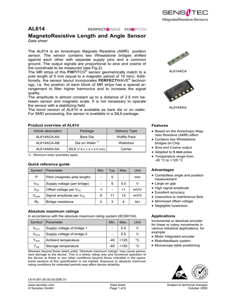
The AL614 is an Anisotropic Magneto Resistive (AMR) position
sensor. The sensor contains two Wheatstone bridges shifted
against each other with separate supply pins and a common
ground. The output signals are proportional to sine and cosine of
the coordinate to be measured (see Fig.2).
The MR strips of this FIXPITCH® sensor geometrically match to a
pole length of 5 mm (equal to a magnetic period of 10 mm). Additionally, the sensor layout incorporates PERFECTWAVE® technology, i.e. the position of each block of MR strips has a special arrangement to filter higher harmonics and to increase the signal
quality.
The amplitude is almost constant up to a distance of 2.5 mm between sensor and magnetic scale. It is not necessary to operate
the sensor with a stabilizing field.
The bond version of AL614 is available as bare die or on wafer.
For SMD processing, the sensor is available in a SIL6 package.
Product overview of AL614
AL614AKA
Features
Article description
Package
Delivery Type
AL614ACA-AA
Bare Die
Waffle Pack
AL614ACA-AB
Die on Wafer 1)
Waferbox
AL614AKA-AA
AL614ACA
SIL6 (7.6 x 1.4 x 3.5 mm)
Based on the Anisotropic Magneto Resistive (AMR) effect
Contains two Wheatstone
bridges on Chip
Sine and Cosine output
Adapted to 5 mm poles
Temperature range from
Carrier
1) Minimum order quantities apply.
-40 °C to +125 °C
Quick reference guide
Symbol
Parameter
Min.
Typ.
Max.
Unit
P
Pitch (magnetic pole length)
-
5
-
mm
VCC
Supply voltage (per bridge)
-
5
5.5
V
Voff
Offset voltage per VCC
-1
-
+1
mV/V
Signal amplitude per VCC
9
11
13
mV/V
Bridge resistance
2
3
4
k
Vpeak
RB
Advantages
Contactless angle and position
measurement
Large air gap
High signal amplitude
Excellent accuracy
Insensitive to interference field
Minimized offset voltage
Negligible hysteresis
Absolute maximum ratings
In accordance with the absolute maximum rating system (IEC60134).
Symbol
Parameter
Min.
Max.
Unit
VCC1
Supply voltage of bridge 1
-
5.5
V
VCC2
Supply voltage of bridge 2
-
5.5
V
Tamb
Ambient temperature
-40
+125
°C
Tstg
Storage temperature
-65
+150
°C
Applications
Incremental or absolute encoder
for linear or rotary movements in
various industrial applications, for
example:
Motor integrated encoder
Motorfeedback system
Microscope table positioning
Stresses beyond those listed under “Absolute maximum ratings” may cause permanent damage to the device. This is a stress rating only and functional operation of
the device at these or any other conditions beyond those indicated in the operational sections of this specification is not implied. Exposure to absolute maximum
rating conditions for extended periods may affect device reliability.
LK14.001.00.00.00.DSE.01
www.sensitec.com
© Sensitec GmbH
Data sheet
Page 1 of 6
Subject to technical changes
October 2009
AL614
MagnetoResistive Length and Angle Sensor (5 mm)
Magnetic data
Symbol
Hext
Parameter
Conditions
Magnetic field strength
Min.
Typ.
Max.
Unit
3
6
-
kA/m
Min.
Typ.
Max.
Unit
-
5
5.5
V
See Fig.2
-1
-
+1
mV/V
Tamb = (-20...+85)°C
-
±3
±10
(µV/V)/K
See Fig.2
9.0
11.0
13.0
mV/V
Tamb = (-20...+85)°C
-4.8
-4.0
-3.2
10-3 /K
2
3
4
k
2.0
2.6
3.2
%/K
Min.
Typ.
Max.
Unit
-
50
-
µm
-
0.1
1
% of Vpeak
1)
1) The stimulating magnetic field in the sensor plane to ensure minimum error specified in note 7.
Electrical data
Tamb = 25 °C; Hext = 25 kA/m; VCC1 = 5 V; VCC2 = 5 V; unless otherwise specified.
Symbol
Parameter
Conditions
VCC
Supply voltage
Voff
Offset voltage per VCC
TCVoff
Vpeak
TCVpeak
RB
TCRB
2) TCVoff =
Temperature coefficient of Voff
Signal amplitude per VCC
2)
3)
Temperature coefficient of Vpeak 4)
Bridge resistance 5)
Temperature coefficient of RB
Voff(T2) - Voff(T1)
T2 - T1
6)
Tamb = (-20...+85)°C
with T1 = -20 °C; T2 = +85 °C.
3) Maximal output voltage without offset influences. Periodicity of Vpeak is sin(2P) and cos(2P).
4) TCVpeak = 100 ·
Vpeak(T2) - Vpeak(T1)
with T1 = -20 °C; T2 = +85 °C.
Vpeak(T1) · (T2 - T1)
5) Bridge resistance between pins 6 and 4, 5 and 4, 2 and 3, and 1 and 7.
6) TCRB = 100 ·
RB(T2) - RB(T1)
RB(T1) · (T2 - T1)
with T1 = -20 °C; T2 = +85 °C.
Accuracy
Tamb = 25 °C; Hext = 25 kA/m; VCC1 = 5 V; VCC2 = 5 V; unless otherwise specified.
Symbol
∆x
k
Parameter
Measurement error
Conditions
7)
Amplitude synchronism
8)
7) ∆x = |xreal - xmeasured| without offset influences due to deviations from ideal sinusoidal characteristics (ascertained at an ideal
magnetic scale).
Vpeak1
8) k = 100 - 100 ·
Vpeak2 .
Dynamic data
Symbol
f
Parameter
Conditions
Frequency range
Min.
Max.
Unit
0
>1
MHz
General data
Symbol
Parameter
Conditions
Min.
Typ.
Max.
Unit
P
Pitch (magnetic pole length)
See Fig.1
-
5
-
mm
d
Distance
See Fig.1
-
1.5
2.5
mm
Tamb
Ambient temperature
-40
-
+125
°C
Tstg
Storage temperature
-65
-
+150
°C
www.sensitec.com
© Sensitec GmbH
Data sheet
Page 2 of 6
Subject to technical changes
October 2009
AL614
MagnetoResistive Length and Angle Sensor (5 mm)
P = 5 mm
d
1
2
3
4
5
6
7
x
0
Fig.1: Arrangement of sensor and magnetic scale. In this example the sensor moves in x-direction along the
fixed scale.
VCC1
100
VCC2
VO2
+VO1
+VO2
-VO1
-VO2
50
Vpeak1
Output voltage (mV)
VO1
Voff1
0
-50
-100
0
GND
2.5
5 (1P)
7.5
10 (2P)
Length x (mm)
Fig.2: left: Simplified circuit diagram.
right: Output signals as function of linear displacements.
www.sensitec.com
© Sensitec GmbH
Data sheet
Page 3 of 6
Subject to technical changes
October 2009
AL614
MagnetoResistive Length and Angle Sensor (5 mm)
AL614 as bare die
Pinning
Pad
Symbol Parameter
1
+VO2
Positive output voltage bridge 2
2
+VO1
Positive output voltage bridge 1
3
-VO1
Negative output voltage bridge 1
4
GND
Ground
5
VCC2
Supply voltage bridge 2
6
VCC1
Supply voltage bridge 1
7
-VO2
Negative output voltage bridge 2
1
2 3 4 5 6
7
Top view
Fig.3: Simplified layout of AL614.
Mechanical data AL614ACA
Sensitive area
5200 ± 100
5003
a
b
2
1
3
4
5
6
I
M
O
1000 ± 100
75 (5)
99 (7)
117 (1)
133 (3)
178 (2, 6)
216 (4)
595
105
95
7
453
2088
2348
2614
2953
3206
4566
Pad
Notes:
!
All dimensions in µm.
Pad dimensioning correlates to pad centre.
The dashed outline drafted the dicing line.
The shaded area denotes the active chip area. This area must not be touched
during handling or assembly since this may cause damage to the chip.
1
2
3
4
5
6
7
axb
125 x 140
90 x 135
95 x 140
93 x 148
100 x 140
100 x 140
138 x 153
Fig.4: Chip outline for AL614ACA as bare die.
Data for Packaging and Interconnection Technologies
Parameter
Value
Unit
Chip area
(5.2 ± 0.1) x (1.0 ± 0.1)
mm2
Chip thickness
525 ± 40
µm
Pad size
See Fig.4
-
Pad thickness
0.6
Pad material
AlCu
www.sensitec.com
© Sensitec GmbH
µm
-
Data sheet
Page 4 of 6
Subject to technical changes
October 2009
AL614
MagnetoResistive Length and Angle Sensor (5 mm)
Mechanical data AL614AKA
Top view
Marker white
Side view
On this side no contact
Bottom view
Notes:
All dimensions in mm.
Pad dimensioning correlates to pad centre.
Pad dimensions: 0.6 mm x 5.5 mm
Active chip area, This area must not be touched during handling or assembly since this may cause damage to the chip
Fig. 5: SIL6 outline for AL614AKA.
www.sensitec.com
© Sensitec GmbH
Data sheet
Page 5 of 6
Subject to technical changes
October 2009
AL614
MagnetoResistive Length and Angle Sensor (5 mm)
General Information
Product Status
The product is in series production. Note: The status of the product may have changed since this data
sheet was published. The latest information is available on the internet at www.sensitec.com.
Right to make changes
Sensitec GmbH reserves the
right to make changes, without
notice, in the products, including software, described or contained herein in order to improve design and/or performance. Sensitec GmbH assumes
no responsibility or liability for
the use of any of these products.
Application Information
Applications that are described
herein for any of these products
are for illustrative purposes
only. Sensitec GmbH makes no
representation or warranty that
such applications will be suitable for the specified use without further testing or modification.
Life critical applications
These products are not qualified for use in life support appliances, aeronautical applications or devices or systems
where malfunction of these
products can reasonably be
expected to result in personal
injury.
Sensitec GmbH
Georg-Ohm-Straße 11
35633 Lahnau
Germany
Solutions for measuring:
Position
Angle
Magnetic field
Current
Fon +49 (0) 64 41/ 97 88-0
Fax +49 (0) 64 41/ 97 88-17
E-Mail info@sensitec.com
www.sensitec.com
Copyright © 2009 by Sensitec GmbH, Germany
All rights reserved. No part of this document may be copied or reproduced in any form or by any means without
the prior written agreement of the copyright owner. The information in this document is subject to change without
notice. Sensitec GmbH does not assume any liability for any consequence of its use.
www.sensitec.com
© Sensitec GmbH
Data sheet
Page 6 of 6
Subject to technical changes
October 2009

