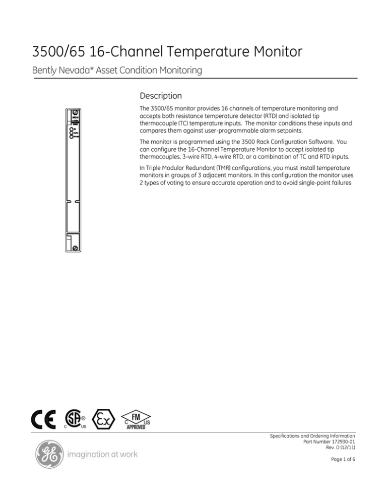
3500/65 16-Channel Temperature Monitor
Bently Nevada* Asset Condition Monitoring
Description
The 3500/65 monitor provides 16 channels of temperature monitoring and
accepts both resistance temperature detector (RTD) and isolated tip
thermocouple (TC) temperature inputs. The monitor conditions these inputs and
compares them against user-programmable alarm setpoints.
The monitor is programmed using the 3500 Rack Configuration Software. You
can configure the 16-Channel Temperature Monitor to accept isolated tip
thermocouples, 3-wire RTD, 4-wire RTD, or a combination of TC and RTD inputs.
In Triple Modular Redundant (TMR) configurations, you must install temperature
monitors in groups of 3 adjacent monitors. In this configuration the monitor uses
2 types of voting to ensure accurate operation and to avoid single-point failures
C
US
Specifications and Ordering Information
Part Number 172930-01
Rev. D (12/11)
Page 1 of 6
Specifications
120 Ω 3-wire and 4wire nickel RTD:
Inputs
-80 °C to +260 °C
Signal
(-112 °F to +500 °F).
Accepts from 1 to 16 RTD or
isolated tip TC transducer signals.
10 Ω 3-wire and 4wire copper RTD:
Input
Impedance
-100 °C to +260 °C,
Greater than 1 MΩ for each lead
input.
Power
Consumption
(-148 °F to +500 °F).
Note:
Platinum RTDs with α = 0.00385 are the worldwide
industrial standard and are the recommended RTDs for all
applications.
Outputs
3 watts nominal.
Transducers
Front Panel
LEDs
OK LED
TCs
Indicates when the temperature
monitor is operating properly.
Type E
-100 °C to +1000 °C,
(-148 °F to +1832 °F).
TX/RX LED
Indicates when the temperature
monitor is communicating with
other modules in the 3500 rack.
Type J
0 °C to +760 °C
(32 °F to +1400 °F).
Bypass LED
Indicates when the temperature
monitor is in Bypass Mode.
Type K
0 °C to +1370 °C
(32 °F to +2498 °F).
RTD CurrentSource Value
913 ± 7 µA @ 25 °C per
transducer (1 supply for the 4wire RTD and 2 supplies for the 3wire).
Type T
-160°C to +400 °C,
(-256 °F to +752 °F).
Signal Conditioning
RTDs
Specified at +25 °C (+77 ° F). Fullscale range for each channel is
set in the field via 3500
Configuration Software. No
calibration is required.
100 Ω 3-wire and 4wire platinum RTD
(α = 0.00385):
-200 °C to +850 °C
(-328 °F to +1562 °F).
100 Ω 3-wire and 4wire platinum RTD
(α = 0.00392):
RTDs and TCs
Resolution
1 °C or 1 °F.
-200 °C to +700 °C
(-328 °F to +1292 °F).
Specifications and Ordering Information
Part Number 172930-01
Rev. D (12/11)
Page 2 of 6
Accuracy
Danger Delay
From 1 to 60 seconds in
0.5-second increments or set to
the minimum alarm delay of 225
mS.
Internal
Termination
Bulkhead Rack: ±3 °C at +25 °C
(±5.4 °F at +77 °F).
Standard Rack: ±3 °C at +25 °C
(±5.4 °F at +77 °F).
External
Termination
Bulkhead Rack: ±3 °C at +25 °C
(±5.4 °F at +77 °F).
Standard Rack: ±3 °C at +25 °C
(±5.4 °F at +77 °F).
Cold Junction Compensation
Sensor (used for TC
measurements)±2 °C at +25 °C
(±3.6 °F at +77 °F).
Proportional Values
Proportional values are temperature measurements
used to monitor the machine. The 16-channel
temperature monitor returns temperature
proportional values.
Environmental Limits
Operating
Temperature
-30 °C to +65 °C (-22 °F to +150
°F).
Storage
Temperature
-40 °C to +85 °C (-40 °F to +185
°F).
Alarms
Alarm
Setpoints:
You can use software
configuration to set Alert and
Danger setpoints for the value
measured by the monitor. Alarms
are adjustable from 0 to 100% of
full-scale for each measured
value. The exception is when the
full-scale range exceeds the
range of the sensor. In this case,
software will limit the setpoint to
the range of the sensor. Accuracy
of alarms are to within 0.13% of
the desired value. The 3500/65
16-channel temperature monitor
has both under- and over-alarm
setpoints.
Alarm Time
Delays
Compliance and Certifications
EMC
Standards:
EN 61000-6-2 Immunity for Industrial Environments
EN 55011/CISPR 11 ISM Equipment
EN 61000-6-4 Emissions for Industrial Environments
European Community Directives:
EMC Directive 2004/108/EC
Electrical Safety
Standards:
EN 61010-1
European Community Directives:
2006/95/EC Low Voltage
Hazardous Area Approvals
You can use software to program
alarm delays as follows:
Alert Delay
North American
Approval Option (01)
Class 1, Div 2
From 1 to 60 seconds in 1-second
increments.
Groups A, B, C, D
T4 @ Ta = -20 °C to +65 ºC
(-4 ºF to +150 ºF)
Specifications and Ordering Information
Part Number 172930-01
Rev. D (12/11)
Page 3 of 6
I/O Modules
North American
Approval Option (02)
Ex nC[L] IIC
Dimensions
(Height x Width
x Depth)
241.3 mm x 24.4 mm x 99.1 mm
Class 1, Zone 2
Class 1, Div 2, Groups A, B, C, D
T4 @ Ta -20 °C to +65 ºC
(-4 ºF to +150 ºF)
ATEX:
(9.50 in x 0.96 in x 3.90 in).
Weight
0.45 kg (1.0 lb.).
Rack Space Requirements
Monitor Module:
Approval Option (02)
1 full-height front slot.
For Selected Ordering Options
with ATEX/North American
agency approvals:
II 3/(3) G
I/O Modules:
1 full-height rear slot.
Ordering Considerations
Ex nC[L] IIC
General
T4 @ Ta = -20 °C to +65 ºC
If you add the 3500/65 to an existing 3500 System
your system will require the following or later
firmware and software versions:
(-4 ºF to +150 ºF)
South Africa
3500/22 Module
Firmware
Approval Option
(02)
For Selected Ordering Options
with ATEX/North American
agency approvals:
Revision 1.50
3500/01
Software
Version 3.85
Ex nCAL [ia] IIC T4
Ex nCAL [L] IIC T4
T4 @ Ta = -20 °C to +65 °C
(-4 °F to +150 °F)
For further certification and approvals information please visit the
following website:
www.ge-mcs.com/bently
3500/02
Software
Not supported*
3500/03
Software
Not supported*
3500/93 Module
Firmware
Monitor Module
Revision 2.02
Dimensions
(Height x Width
x Depth)
System 1*
Software
241.3 mm x 24.4 mm x 241.8 mm
(9.50 in x 0.96 in x 9.52 in).
Weight
Revision 5.2 with Service Pack 2
*Attempting to use the 3500/65 with 3500/02 or 3500/03
software may prevent proper operation of the software.
0.91 kg (2.0 lb.).
Specifications and Ordering Information
Part Number 172930-01
Rev. D (12/11)
Page 4 of 6
You cannot use external termination blocks with
internal termination I/O modules.
When ordering I/O Modules for use with 4-Wire
RTDs, order with Modification 179952-01. For further
information, see the 3500/65 Manual.
0005
0007
0010
0025
0050
0100
B: Assembly Instructions
01
02
Ordering Information
Spares
When ordering I/O Modules with external
terminations, you must order the external
termination blocks and cables separately.
3500/65-AXX-BXX
A: I/O Module Type
5 feet (1.5 metres)
7 feet (2.1 metres)
10 feet (3 metres)
25 feet (7.5 metres)
50 feet (15 metres)
100 feet (30.5 metres)
Not Assembled
Assembled
172931-01
3500/65 Manual.
01
02
RTD/Isolated Tip TC with
Internal Terminations
RTD/Isolated Tip TC with
External Terminations
B: Agency Approval Option
00
None
01
CSA/NRTL/C
02
CSA/ATEX
145988-02
3500/65 Monitor.
172103-01
3500/65 RTD/Isolated Tip TC I/O
Module, Internal Terminations
173005
Connector Header, Internal
Termination, 20-position, Black
Note: Agency Approval Option B 02 is only
available with Ordering Option A 01.
External Termination Block
172109-01
3500/65 RTD/ Isolated Tip TC I/O
Module, External Terminations
172115-01
RTD/Isolated Tip TC External
Termination Block (Euro Style
connectors).
Cables
172115-01
RTD/Isolated Tip TC External
Termination Block (Euro Style
Connectors)
3500/65 Transducer (XDCR) Signal to External
Termination (ET) Block Cable
134544-AXXXX-BXX
A: Cable Length
Specifications and Ordering Information
Part Number 172930-01
Rev. D (12/11)
Page 5 of 6
Graphs and Figures
1.
Status LEDs
2.
3500/65 Main Module Front View
3.
RTD/ Isolated Tip TC I/O Module (Internal Terminations)
4.
RTD/ Isolated Tip TC I/O Module(External Terminations)
Figure 1: Front and rear views of the 3500/65 16 Channel Temperature Monitor
* Denotes a trademark of Bently Nevada, Inc., a wholly owned subsidiary of General Electric Company.
© 2006 – 2011 Bently Nevada, Inc. All rights reserved.
Printed in USA. Uncontrolled when transmitted electronically.
1631 Bently Parkway South, Minden, Nevada USA 89423
Phone: 775.782.3611
Fax: 775.215.2873
www.ge-mcs.com/bently
Specifications and Ordering Information
Part Number 172930-01
Rev. D (12/11)
Page 6 of 6


