Pico Load Assembly Instructions
advertisement

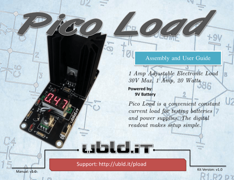
Assembly and User Guide 1 Amp Adjustable Electronic Load 30V Max, 1 Amp, 20 Watts Powered by: 9V Battery Pico Load is a convenient constant current load for testing batteries and power supplies. The digital readout makes setup simple. Support: http://ubld.it/pload Manual: v1.0 Kit Version: v1.0 Tool Checklist 1. Soldering Iron 2. Wire Cutters We recommend the Hakko FX888 or similar iron with a chisel tip. Small cutters for clipping excess wire leads after soldering. 4. 5. Multimeter Multimeter for verifying component values and adjusting the circuit. Wire Strippers 18 AWG Wire Strippers for removing insulation from wires. |2| 3. Solder Electronic solder is used for soldering parts to the PCB. |3| BOM is short for Bill of Materials. Check each line item as you verify the required quantity of components. Line Designator Description Required Kit Qty 1 B1 9V Battery Holder 1 1 2 C1, C3, C4 .1uF 50V Disc Capacitor 3 3 3 C2 100pF 50V Disc Capacitor 1 1 4 D1 1N914 Small Signal Diode 1 1 5 HS1 Black Anodized Heat Sink 1 1 6 J1, J2 Banana Jack 2 2 |3| Line Designator Description Required Kit Qty 7 LED1 3 Wire Digital Meter 1 1 8 Q1 IRF520 1 1 9 R1 1 Ohm 1 W 1% Resistor 1 1 10 R2 100 Ohm 1/4W Resistor 1 1 11 R3, R4 1K 1/4W Resistor 2 2 12 R5 2K Ohm Potentiometer 1 1 |4| 13 R6 6.8K Ohm 1/4W Resistor 1 1 |4| Line Designator Description Required Kit Qty 14 S1 Slide Switch 1 1 15 U1 LM358N 1 1 16 U2 L78L05ACZ 1 1 17 M1 TO-220 Heat Sink Assembly 1 1 18 Tape Double Sided Tap 1 2 |5| |5| Before we locate the first component let’s take a minute to review the proper way to insert and solder the components to your circuit board. Insert the components into the circuit board. Bend the component leads to hold the component in place while soldering. Flip the board and solder the component leads . Trim the component leads at the top of the solder joint. |6| Solder the 1 Ohm 1 Watt Resistor into R1. The first component to locate is a one 1 Ohm 1 Watt Resistor (line #9). Highlighted Axial Lead Resistors such as the ones used in this kit are color coded. Compare the resistor you are installing to the images shown in each step. Also double check the values with a multimeter on the ohm setting. |7| Solder the 100 Ohm ¼ Watt Resistor into R2. Locate one 100 Ohm ¼ Watt Resistor (line #10). Take pride in your work. Take your time to bend all the components leads to 90 degree angles using needle nose pliers. |8| Solder the 1K Ohm ¼ Watt Resistors into R3, R4. Locate two1K Ohm ¼ Watt Resistors (line #11). It’s not necessary for resistors, but inserting them all in the same direction will make your board look that much better. Use the last band (tolerance band) as a reference for the orientation. |9| Solder the 6.8k Ohm ¼ Watt Resistor into R6. Locate one 6.8k Ohm ¼ Watt Resistors (line #13). For better looking solder joints use Kester #2331-ZX water soluble flux pen on every pad before applying solder. Flux removes oxidation and allows heat to transfer from your iron to the pad. |10| Solder the .1uF 50V Disc Capacitor into C1, C3, and C4 Locate three .1uF 50V Disc Capacitors (line #2). Ceramic capacitors are not polarized so orientation doesn’t matter. |11| Solder the 100pF 50V Disc Capacitor into C2. Locate one 100pF 50V Disc Capacitor (line #3). Capacitors store an electrical charge much like your body builds and stores static. It’s also good to know that since a capacitor takes time to charge and discharge it’s said that it opposes changes in voltage. |12| Solder the 1N914 Small Signal Diode into D1. Locate one 1N914 Small Signal Diode (line #4). Diodes are polarized. The narrow band around this diode is the cathode and should be aligned with the stripe on the circuit board. |13| Solder the LM358N into U1. Locate one LM358N (line #15). Pin one of the IC is marked with a small indentation in the package. Orient the package indentation with the silkscreen indentation. |14| Solder the L78L05ACZ U2 Locate one L78L05ACZ (line #16). U2 is a 5V Regulator in a TO-92 package. This small package also has current limiting and thermal protection making virtually indestructible. |15| Solder the Slide Switch into S1 Locate one Slide Switch (line #14). SW is used to turn the circuit on and off. It’s a good idea to turn R5 full counter clockwise (down) before turning power on. |16| Insert the Red Banana Jack in the hole marked with a + and the Black Banana Jack in the hole marked with a -. Secure with the nuts supplied. Locate two Banana Jacks (line #6). The banana jacks are where you will attach your power source to be tested. |17| Solder the 2k Ohm Potentiometer into R5 Locate one 2k Ohm Potentiometer (line #12). R5 is used to set the desired current draw. |18| Attach Q1 (IRF520) to HS1 (Heat Sink) using M1 (TO-220 Mounting Hardware). First place the thermal pad between Q1 and the Heat Sink. Then insert the 3mm screw through the white plastic insulating bushing and insert that into Q1. Attach Q1 to the Heat Sink with the leads towards the mounting pins of the Heat Sink. Secure the assembly with the 3mm Hex Nut leaving it a little loose until everything has been soldered into the PCB. Finish tightening the screw and nut after your solder the assembly to the PCB. This will make for easier alignment. |19| Solder the Q1 and HS1 Assembly into the respective holes. Adding a Fan to the heat sink and adding additional 1 Ohm 1 Watt resistors in parallel for R1 will allow it to dissipate more than the rated 20 Watts. |20| Solder LED1 (Digital Meter) to B (Black), R (Red), and W (White) and adhere it to the circuit board with the provided double sided tape. Locate one 3 Wire Digital Meter and Double Sided Tape (line #3). Cut the wires short enough but not too short. A little slack is better than having your display off center. |21| Install the Battery Holder into B1. You will probably want to cut the wires very short . Attach the battery holder with double sided tape. Locate one 9V Battery Holder Warning: Make sure your battery is good. The digital meter is powered directly from the 9V battery and low voltage will throw off the readings. |22| Visit the Community Support Forums: http://ubld.it/pload (Optional) Hack: Installing 4x 1 Ohm 1 Watt resistors in parallel for R1 will increase the max current allowed to about 4 Amps. Your final assembly should look like this. Double check all polarized components such as D1. |23|


