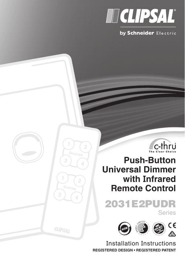
Push-Button
Universal Dimmer
with Infrared
Remote Control
2031E2PUDR
Series
Installation Instructions
REGISTERED DESIGN • REGISTERED PATENT
2031E2PUDR Series Push-Button Universal Dimmer Installation Instructions
Table of Contents
1.0
Product Range...................................................................................................................3
2.0Description.........................................................................................................................3
3.0
Dimmer Unit Operation.....................................................................................................4
4.0
Using the Remote Control................................................................................................5
4.1 Programming the Device Buttons on the Remote Control............................................5
4.2 Programming the Scene Buttons on the Remote Control.............................................5
4.3 Clearing the Preset Program for an IR Remote Control Button...................................6
4.4 Exiting Programming Mode..........................................................................................6
5.0
Dimming Applications......................................................................................................6
6.0
Installation Instructions...................................................................................................8
7.0
Important Features...........................................................................................................9
7.1 Soft Start Feature.........................................................................................................9
7.2 Minimum Brightness Settings.......................................................................................9
7.3 Thermal Overload Protection Circuitry.........................................................................9
8.0
Load Compatibility........................................................................................................ 10
9.0
Incompatible Loads...................................................................................................... 10
10.0 Important Warning........................................................................................................ 10
11.0 Product Specifications................................................................................................. 11
12.0 Warranty Statement.........................................................................................................12
Copyright Notice
The concepts, products and designs described in this document are the subject of
international patents, and protected by international law. Copyright Schneider Electric. All
rights reserved.
Trademarks
• Clipsal is a registered trademark of Schneider Electric.
• C-Thru® - The Clear Choice is a registered trademark of Schneider Electric.
All other logos and trademarks are the property of their respective owners.
Disclaimer
Schneider Electric reserves the right to change specifications or designs described in this
manual without notice and without obligation.
2 of 12
© 2013 Schneider Electric. All Rights Reserved.
2031E2PUDR Series Push-Button Universal Dimmer Installation Instructions
1.0 Product Range
2031E2PUDR
Push-Button Universal Dimmer c/w IR Remote Control, 450W (2000 Series)
C2031E2PUDR
Push-Button Universal Dimmer c/w IR Remote Control, 450W (Classic Series)
SC2031E2PUDR
Push-Button Universal Dimmer c/w IR Remote Control, 450W (Slimline Series)
SL2031E2PUDR Push-Button Universal Dimmer c/w IR Remote Control, 450W (Eclipse Series)
31E8TXIR
Infrared Remote Control, 8 Button (Spare Part)
*Please note: all above products are supplied with an infrared remote control included in the
package. Additional remote controls are available (cat-number 31E8TXIR).
2.0 Description
The Clipsal 2031E2PUDR Series Push-Button Universal Dimmer represents the next
generation of smart dimming products. The unit features a unique push-button design, with
multi-segment LED display to indicate the load status.
The unit also features a handy infrared remote control. Compact in size, the remote control
is surprisingly powerful. It is capable of controlling up to four dimmer units and can even set
preset lighting ‘scenes’ at the touch of a button.
6
7
4
2
1
5
3
Dimmer Unit
IR Remote Control
1. IR Receiver : receives infrared signal from the IR remote control.
2. LED Indicator : indicates the current dimming level.
3. Surround : removable frame covers the mounting screws.
4. IR Device Keys : control individual lights using the remote control.
5. IR Scene Keys : activate lighting scenes using the IR remote control.
6. IR Transmitter : transmits infrared signals to the IR receiver.
7. Programming Button : used to set up purposes.
The dimmer unit is based on Clipsal’s patented Universal Dimmer Technology. It can provide
full control of almost any type of load, whether it be incandescent lighting, 240V halogen or
dichroic lamps, iron-core or electronic low voltage lighting transformers as used in downlight
applications. Even small motor loads such as ceiling sweep and exhaust fans can be
controlled.
C-Thru® The Clear Choice - helping you select the right dimmer, first time, every time.
© 2013 Schneider Electric. All Rights Reserved.
3 of 12
2031E2PUDR Series Push-Button Universal Dimmer Installation Instructions
3.0 Dimmer Unit Operation
Push-Button Operation
• Tap the push-button to turn the dimmer ON or OFF.
SHORT
PRESS
• The dimmer has memory and will remember the previous dim setting.
• When you tap the button to turn the light OFF, the unit will store the
current setting in memory. When you tap the button to turn the light
ON, the dimmer will restore the previous dim setting.
• Press and hold the button to dim up and down. Release the button to
stop dimming.
LONG
PRESS
• The dimmer will cycle up and down alternately. When the light is ON, the dimmer will dim down by default. When the dimmer is OFF, it will
dim upwards (increase brightness) by default. A subsequent long
press will dim in the opposite direction.
• If the dimmer reaches its maximum or minimum brightness level,
the unit will pause for 1 second, then start dimming in the
opposite direction.
• A single ramp cycle takes about 10 seconds to complete. If the button
is not pressed for 15 seconds, the dimming is set to fade out by
default again.
DOUBLECLICK
• Tap the button twice to turn the dimmer ON to 100% brightness. The
dimmer will reach maximum brightness in approximately 4 seconds.
LED Indicators
The unit incorporates five LED segments to display the set
dimming level.
Each LED represents approximately 20% increments in the
output brightness. The brighter the output the more LEDs will
be illuminated - just like a bar graph.
When the dimmer is turned OFF, the LED indicators will glow
slightly. This shows the stored dimmer level that will be activated
on the next short press operation.
Power Failure
When recovering from a power failure, the unit will restore the last dim level after a 10
second delay. Pressing the button will cancel this delay. The IR remote control does not work
during this delay.
4 of 12
© 2013 Schneider Electric. All Rights Reserved.
2031E2PUDR Series Push-Button Universal Dimmer Installation Instructions
4.0 Using the Remote Control
Operating the device buttons on the IR remote control is similar to using the push-button on
the front of the dimmer unit, except that the IR remote control does not support the doubleclick operation.
The device buttons can be programmed to control up to four different Dimmer Units.
Scene buttons allow the user to program up to four preset lighting levels into the memory.
4.1 Programming the Device Buttons on the Remote Control
By default, the dimmer is programmed to use the device 1 button on the remote control.
Follow the procedure below to assign other dimmer units to device buttons 2 through to 4.
Keep pointing the IR remote control at the IR receiver on the dimmer during programming.
1. Press the programming button on the side of the remote. The LED indicators on the dimmer unit will flash rapidly.
2. Press the desired device button on the remote control. The LED indicators on the dimmer will flash slowly.
3. Press the push-button on the dimmer unit that you want to control. The LED indicators will stop flashing. The dimmer unit is now programmed to respond to the selected device button on the remote control.
4.2 Programming the Scene Buttons on the Remote Control
Up to four preset dimming levels can be programmed into the dimmer unit using the
scene buttons.
Keep pointing the IR remote control at the IR receiver on the dimmer during programming.
1. Set the desired dim level for the desired scene button.
2. Press the programming button on the side of the remote. The LED indicators on the dimmer unit will flash rapidly.
3. Press the desired scene button on the remote control. The LED indicators on the dimmer will flash slowly.
4. Press the push-button on the dimmer unit that you want to control. The LED indicators will stop flashing. The dimmer unit is now programmed to respond to the selected scene button on the remote control.
Note:
• During the programming procedure, if no button is pressed within 10 seconds then the dimmer unit will return to normal mode.
• If more than one device or scene button is pressed on the IR remote control during programming, then the dimmer will respond to the latest press.
© 2013 Schneider Electric. All Rights Reserved.
5 of 12
2031E2PUDR Series Push-Button Universal Dimmer Installation Instructions
4.3 Clearing the Preset Program for an IR Remote Control Button
Keep pointing the IR remote control at the IR receiver on the dimmer during programming.
1. Press the programming button on the side of the remote. The LED indicators on the dimmer unit will flash rapidly.
2. Press the device or scene button on the remote control that you wish to clear the preset program. The LED indicators on the dimmer will flash slowly.
3. Double click the push-button on the dimmer unit to delete the preset program associated with the IR remote control button.
4.4 Exiting Programming Mode
The dimmer allows the user to exit programming mode without making changes. To do this
the user can do one of the following things:
• press the programming button on the side of the remote control a second time
• wait for 10 seconds and the unit will automatically exit programming mode.
5.0 Dimming Applications
The powerful infrared remote control facility offers ultimate flexibility, allowing a number of
different dimming scenes to be implemented - from the simple to the sophisticated.
To inspire creativity, some examples are shown on the following pages.
Dimming one light, with four
different preset scenes.
25%
50%
75%
100%
Dimming multiple dimmers
individually from one remote.
6 of 12
© 2013 Schneider Electric. All Rights Reserved.
2031E2PUDR Series Push-Button Universal Dimmer Installation Instructions
Setting a preset for each
dimmer individually.
Dimming control
of multiple dimmer
units from a single
device button.
Setting a scene across
multiple dimmers.
© 2013 Schneider Electric. All Rights Reserved.
7 of 12
2031E2PUDR Series Push-Button Universal Dimmer Installation Instructions
Setting a scene across
multiple dimmers
(all OFF function).
Using multi-gang
surrounds (available for
Clipsal 2000 Series only).
6.0 Installation Instructions
Wiring Diagram
Active/Line
LINE
2031E2PUDR Series
1 Gang IR Dimmer
Neutral
LOAD
Min. Load:
25VA
Max. Load:
450VA
220-240V a.c. 50Hz
IEC 60669-2-1
Wire Strip Length
10mm
8 of 12
Lamp
LOOP
UP
© 2013 Schneider Electric. All Rights Reserved.
2031E2PUDR Series Push-Button Universal Dimmer Installation Instructions
7.0 Important Features
7.1 Soft Start Feature
The Clipsal Universal Dimmer incorporates a soft start feature, providing a noticeably
smooth lamp illumination at turn on. This feature also minimises lamp filament start-up
stress, which may increase lamp life.
7.2 Minimum Brightness Settings
The minimum brightness level has been factory preset to suit most applications.
Note: exercise care when connecting small motor loads. Test to make sure the motor does
not stall at low output settings. Use the scene buttons to set up preset fan speeds
as required.
7.3 Thermal Overload Protection Circuitry
The Clipsal 2031E2PUDR Series Dimmer incorporates three levels of overload protection:
Short Circuit Protection
The unit features short circuit protection, designed to ensure the dimmer can survive in
case of wiring fault or catastrophic failure of the load. Resets automatically once short
circuit conditions are removed.
Thermal Overload Compensation
Automatically reduces lamp brightness should the dimmer be inadvertently overloaded.
Resets automatically once overload conditions are corrected.
Thermal Cut-Out
The unit contains a non-resettable thermal fuse device, designed to blow in case of
catastrophic circuit failure. This is a secondary protection measure, intended to operate
as a backup in case of persistent or prolonged overload conditions. If the thermal cutout fuse blows, then the dimmer will be rendered permanently inoperable and must
be replaced.
Note: any significant overload should be avoided in order to prevent damage to the load,
fixed wiring of the installation or other hardware connected to the affected circuit.
© 2013 Schneider Electric. All Rights Reserved.
9 of 12
2031E2PUDR Series Push-Button Universal Dimmer Installation Instructions
8.0 Load Compatibility
The Clipsal 2031E2PUDR Series Universal Dimmer is a part of the C-Thru® Dimmer range
and is compatible with a wide range of load types.
C-THRU® COLOUR
LOAD
SYMBOL
COMPATIBLE
LOADS
Incandescent lighting
halogen/dichroic 240V lamps
Low voltage halogen/
dichroic lighting with iron-core
transformers
Low voltage halogen/dichroic
lighting with electronic
transformers
M
Small motor loads:
-exhaust fans
(shaded pole induction motors)
-ceiling fans
(split-phase induction motors)
BLUE
GREEN
AMBER
TRANSPARENT
LEADING
EDGE
DIMMER
TRAILING
EDGE
DIMMER
FAN
SPEED
CONTROLLER
UNIVERSAL
DIMMER
450W
450W
500W
450W
✓
✓
8
✓
8
✓
8
8
8
✓
✓
✓
8
8
✓
✓
IMPORTANT NOTES
• Any number of low voltage lighting transformers can be used, providing the total lamp wattage does not exceed the maximum load rating of the dimmer.
• Mixed load types are permitted in any combination, providing the total lamp wattage does not exceed the maximum load rating of the dimmer. Example: lighting circuit comprising a combination of both iron-core and electronic transformers.
•
It is recommended that when using electronic transformers, each be loaded to at least 75% of its maximum rated load. This reduces the possibility of lamp flicker when dimming, as is common with some transformers. Refer to the manufacturer’s specifications for the transformer being used.
• When controlling small motor loads, such as ceiling sweep fans and exhaust fans, it is recommended to test the fan thoroughly to ensure reliable motor start at minimum brightness. Use the scene facility to select preset speeds as required.
9.0 Incompatible Loads
Exercise care when using compact fluorescent or fluorescent load types. Use only lamps/
ballasts that are compatible with phase angle control (leading or lagging). Refer to the lamp
/ballast manufacturer’s specifications for recommendations. Dimmer warranty is void when
controlling incompatible load types, as determined by Schneider Electric.
10.0 Important Warning
It is illegal for persons other than an appropriately licensed electrical contractor or other
persons authorised by legislation to work on the fixed wiring of any electrical installation.
Penalties for conviction are severe!
10 of 12
© 2013 Schneider Electric. All Rights Reserved.
2031E2PUDR Series Push-Button Universal Dimmer Installation Instructions
11.0 Product Specifications
Parameter
Value
Universal Dimmer
Nominal Operating Voltage
220 - 240V a.c.
Nominal Operating Frequency
50 Hz
Maximum Load
450W
(1.8A)
Minimum Load
25W
(0.1A)
Dimming Technique
Leading edge/trailing edge phase control
(dynamically auto selected)
Dimming Range
Approximately 20 - 97%
Incandescent lighting
Halogen 240V lamps
Low voltage lighting with electronic
transformers
Compatible Loads
Low voltage lighting with iron-core
transformers
M
Incompatible Loads
Small motor loads
-exhaust fans
(shaded pole induction motors)
-ceiling fans
(split-phase induction motors)
Fluorescent lighting
Mounting Centres
84mm
Australian Pattern Plate
Infrared Remote Control
Power Supply
3V CR2025 battery (supplied)
Transmission Media
Infrared light, wavelength 940nm
Transmission Range
16m maximum at right angles to the plate,
9m at 45 degrees to the plate
Carrier Frequency
38 kHz
Dimensions
86mm x 33mm x 8.1mm
General
Operating Humidity Range
10 to 90% R.H.
Operating Temperature Range
0 - 40°C
Storage Temperature Range
0 - 60°C
Standards Compliance
AS/NZS3100
AS/NZS CISPR15
IEC60669-2-1
Electrical Safety
Emission Compliance
Electronic Switches
Specifications typical @ 240V , 25°C ± 5°C
No user serviceable parts inside
© 2013 Schneider Electric. All Rights Reserved.
11 of 12
12.0 Warranty Statement
1. The benefits conferred herein are in addition to, and in no way shall be deemed to
derogate; either expressly or by implication, any or all other rights and remedies in
respect to the Clipsal product, which the consumer has under the Commonwealth Trade
Practices Act or any other similar State or Territory Laws.
2. The warrantor is Schneider Electric. With registered offices in all Australian States.
3. This by Schneider Electric product is guaranteed against faulty workmanship and
materials for a period of two (2) years from the date of installation.
4. Schneider Electric reserves the right, at its discretion, to either repair free of parts and
labour charges, replace or offer refund in respect to any article found to be faulty due to
materials, parts or workmanship.
5. This warranty is expressly subject to the by Schneider Electric product being installed,
wired, tested, operated and used in accordance with the manufacturer’s instructions.
6. All costs of a claim shall be met by Schneider Electric, however should the product that
is the subject of the claim be found to be in good working order all such costs shall be
met by the claimant.
7. When making a claim the consumer shall forward the by Schneider Electric product to
the nearest office of Schneider Electric (Australia) Pty Ltd with adequate particulars of
the defect within 28 days of the fault occurring. The product should be returned securely
packed, complete with details of the date and place of purchase, description of load, and
circumstances
of malfunction.
Schneider Electric (Australia) Pty Ltd
Contact us: clipsal.com/feedback
National Customer Care Enquiries:
Tel 1300 2025 25
Fax 1300 2025 56
Schneider Electric (Australia) Pty Ltd reserves the right to change specifications, modify designs
and discontinue items without incurring obligation and whilst every effort is made to ensure that
descriptions, specifications and other information in this catalogue are correct, no warranty is given in
respect thereof and the company shall not be liable for any error therein.
© 2013 Schneider Electric. All Rights Reserved.
Trademarks are owned by Schneider Electric Industries SAS or its affiliated companies.
F2183/03
SEAU 26762 September 2013


