Mechatronic
pressure measurement
Differential pressure switch
Ex protection EEx-d, IP 65, for low pressure ranges
Model DA10
WIKA data sheet PV 35.45
Applications
■■ Differential pressure monitoring and direct switching of
electrical loads
■■ For gaseous and liquid, aggressive and highly viscous or
contaminated media, also in aggressive ambience
■■ Process industry: Chemical/petrochemical, on- and
offshore, technical gases, environmental technology,
machine building and general plant construction, water
treatment, pharmaceutical industry
■■ Pump monitoring and control / filter monitoring, level
measurement in closed tanks
■■ Ignition protection type GAS Ex-d DUST Ex-tD Gr. II Cat.
1/2 GD
Special features
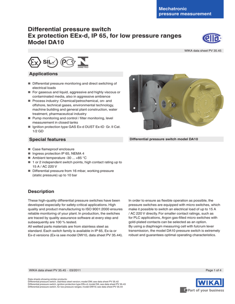
Differential pressure switch model DA10
■■ Case flameproof enclosure
■■ Ingress protection IP 65, NEMA 4
■■ Ambient temperature -30 ... +85 °C
■■ 1 or 2 independent switch points, high contact rating up to
15 A / AC 220 V
■■ Differential pressure from 16 mbar, working pressure
(static pressure) up to 10 bar
Description
These high-quality differential pressure switches have been
developed especially for safety-critical applications. High
quality and product manufacturing to ISO 9001:2000 ensures
reliable monitoring of your plant. In production, the switches
are traced by quality assurance software at every step and
subsequently are 100 % tested.
All wetted parts materials are from stainless steel as
standard. Each switch family is available in IP 65, Ex-ia or
Ex-d versions (Ex-ia see model DW10, data sheet PV 35.44).
WIKA data sheet PV 35.45 ∙ 03/2011
Data sheets showing similar products:
Differential pressure switch, stainless steel version; model DW; see data sheet PV 35.42
Differential pressure switch, ignition protection type EEx-d; model DA; see data sheet PV 35.43
Differential pressure switch, for low pressure ranges; model DW10; see data sheet PV 35.44
In order to ensure as flexible operation as possible, the
pressure switches are equipped with micro switches, which
make it possible to switch an electrical load of up to 15 A
/ AC 220 V directly. For smaller contact ratings, such as
for PLC applications, Argon gas-filled micro switches with
gold-plated contacts can be selected as an option.
By using a diaphragm measuring cell with fulcrum lever
transmission, the model DA10 pressure switch is extremely
robust and guarantees optimal operating characteristics.
Page 1 of 4
Standard version
Case
Aluminium, epoxy resin coated,
case cover with screw-type cover, due to anti-twist device
secured against unauthorised intervention
Ingress protection
IP 65 per EN 60529 / lEC 529
Switch contacts
one or two SPDT (change-over) micro switches selectable,
DPDT function through two SPDT
Code Switch
micro switches with simultaneous
U
1 x SPDT
triggering within 0.5 % of span, in the
following variants:
D
2 x SPDT
Code Design
Permissible temperature
Ambient: -30 ... +85 °C
AC
1
Process connection
Stainless steel, lower mount (LM)
2 x ¼ NPT (female)
Measuring system
Diaphragm measuring cell with fulcrum lever transmission
5
0 ... 16 mbar
0 ... 25 mbar
0 ... 40 mbar
0 ... 60 mbar
Page 2 of 4
2 switch
contacts
1.2 mbar
1.2 mbar
1.6 mbar
2.0 mbar
1.6 mbar
1.6 mbar
2.2 mbar
2.5 mbar
0.25 A, 220 V
Gold-plated contacts
Silver contacts
inert gas filled
1 A, 125 V 0.5 A, 24 V
15 A, 220 V 2 A, 24 V
0.5 A, 220 V
Gold-plated contacts
inert gas filled
1 A, 125 V
Tamb: -30 ... +70 °C
0.5 A, 24 V
Adjustable switch hysteresis
20 A, 220 V 2 A, 24 V
Silver contacts 1)
0.5 A, 220 V
1) Max. 1 switch contact
2) Only the underlined data are shown on the product label
Repeatability
≤ 1 % of span
Setting ranges, max. switch hysteresis
1 switch
contact
DC
Fixed switch hysteresis
Silver contacts
15 A, 220 V 2 A, 24 V
0.5 A, 125 V
Tamb: -30 ... +70 °C
Max. working pressure (static pressure)
Either side
max. 10 bar
Code: 10
Max. switch hysteresis
2
3
4
Wetted parts
Process connection: Stainless steel 304
Diaphragm:
Stainless steel 316
Sealing:
NBR
Setting range
Electrical rating
(resistive load) 2)
1 switch contact
with settable
hysteresis
Note
If the switch point is below 10 % of the span, the pressure
switch should be mounted vibration-free in order to avoid any
accidental switching.
- ... 3 ... 8 mbar
4 ... 11 mbar
5 ... 14 mbar
WIKA data sheet PV 35.45 ∙ 03/2011
Switch points
The switch points can be set to your requirements, free-ofcharge.
Please specify:
Switch point, switching direction for each contact (e.g. switch
point 1: 0.5 bar, falling, switch point 2: 3 bar, rising)
With two micro switches, the switch points can be set
independently of each other.
After unscrewing the case cover, switch point adjustment
can be made using the adjustment screw. The switch point is
settable within the entire measuring range with the following
general rule:
■■ Define the value A = 2x repeatability + switch hysteresis
■■ If the pressure is rising, the switch point should be set
between (min. + value A) up to max. of the setting range
■■ If the pressure is falling, the switch point should be set
between min. up to (max. - value A) of the setting range
Example:
Setting range: 0 ... 1 bar with one switch contact
Repeatability: 1 % of 1 bar = 10 mbar
Switch hysteresis = 15 mbar (see table setting ranges)
Value A = 2 x 10 mbar + 15 mbar = 35 mbar
If the pressure is rising, the switch point should be set
between 35 mbar up to 1 bar.
If the pressure is falling, the switch point should be set
between 0 up to 965 mbar.
For optimal performance we suggest the switch point lies
between 25 % and 75 % of the setting range.
Options
■■ Other process connection, also with adapter
■■ Electrical connection 3/4 NPT, G 1/2, G 3/4 or M20 x 1.5
(female)
■■ Cable gland on request
■■ 2" pipe-mounting kit (with clamping element)
■■ Version for off-shore 3) or tropicalised application 3)
■■ Accessories:
- Three-way or five-way valve
3) Inert gas filled contacts required
Approvals and certificates
■■ GOST-R certificate
■■ Test certificate *CA* (confirmation of the switching accura-
cy)
■■ Test report *CP* (3-time listing of the switch point, requires
switch point specification)
■■ Material certificate 3.1 per EN 10204
Electrical connection
½ NPT female, cable connection using internal terminal
block, protective conductor connection using internal and
external screw, max. earth cable cross-section 4 mm2
Pressure switch certified per:
■■ Pressure equipment directive 97/23/EC (PED, annex 1,
category IV, safety accessories, module B + D)
■■ Low voltage directive 73/23 EEC and 93/68 EEC
Dielectric strength
Safety class I (EN 61298-2: 1997-06)
Mounting
Direct or wall mounting
Preferred connection location of the process connection
should be below.
Weight
approx. 10 kg
WIKA data sheet PV 35.45 ∙ 03/2011
Page 3 of 4
Dimensions in mm
Cable gland
Ordering information
Model / Switch contacts with version / Setting range / 2 x Process connection / Electrical connection / Switch point(s) /
Switching direction(s) / Options
Example: DA10 - U1 - 0/16 mbar - 2 x 1/4" NPT-F - 1/2" NPT-F
© 2011 WIKA Alexander Wiegand SE & Co. KG, all rights reserved.
The specifications given in this document represent the state of engineering at the time of publishing.
We reserve the right to make modifications to the specifications and materials.
WIKA data sheet PV 35.45 ∙ 03/2011
03/2011 GB
Page 4 of 4
WIKA Alexander Wiegand SE & Co. KG
Alexander-Wiegand-Straße 30
63911 Klingenberg/Germany
Tel.
(+49) 9372/132-0
Fax
(+49) 9372/132-406
E-mail info@wika.de
www.wika.de

