Reclosers
Electrical Apparatus
Types NOVA15, NOVA27, and NOVA38
Three-Phase, Microprocessor-Controlled
280-42
DESCRIPTION
The Kyle Type NOVA three-phase,
electronically controlled, vacuuminterrupting automatic circuit
reclosers provide reliable, economical overcurrent protection, advanced
metering, and automation systems
for distribution circuits rated through
34.5 kV.
The NOVA recloser combines solid
cycloaliphatic-epoxy polymerencapsulated vacuum interrupters
with a reliable, lightweight operating
mechanism that utilizes a magnetic
actuator to provide a lifetime of trouble-free operation. The solid polymer
system does not rely on a gaseous,
liquid, or foam dielectric. The Type
NOVA recloser is highly resistant to
ozone, oxygen, moisture, contamination, and ultraviolet light.
The Type NOVA recloser is available
with two configuration options: controlpowered interface and auxiliary-powered interface. Designed and tested
to be compatible with Cooper Power
Systems three-phase controls, these
automatic circuit reclosers offer
superior coordination, protection,
and application capabilities.
Recloser operations are programmed in an electronic control
with accurate characteristics and a
host of advanced features. Precise
operating tolerances enable close
coordination with other protective
devices on the system. When system
requirements change, program settings are easily altered with no sacrifice of accuracy or consistency.
Compact and lightweight, NOVA
reclosers are easily installed on poles
or in substations. Mounting equipment is available for both pole and
substation applications.
Recloser and control accessories
enable further tailoring of the protective program to achieve maximum
system operating flexibility.
July 2009 • Supersedes 12/2004
Printed in USA
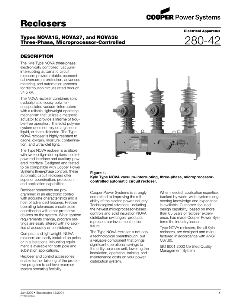
Figure 1.
Kyle Type NOVA vacuum-interrupting, three-phase, microprocessorcontrolled automatic circuit recloser.
Cooper Power Systems is strongly
committed to improving the reliability of the electric power industry.
Technological advances, including
the newest microprocessor-based
controls and solid insulation NOVA
distribution switchgear products,
represent our investment in the
future.
The Type NOVA recloser is not only
a technological breakthrough, but
a valuable component that brings
significant operational savings to
the utility business unit, lowering the
installation, operation, training, and
maintenance costs on your power
distribution system.
When needed, application expertise,
backed by world-wide systems engineering knowledge and experience,
is available. Customer-focused
design capability, based on more
than 65 years of recloser experience, has made Cooper Power Systems the industry leader.
Type NOVA reclosers, like all Kyle
reclosers, are designed and manufactured in accordance with ANSI
C37.60.
ISO 9001:2000 Certified Quality
Management System
1
Types NOVA15, NOVA27, and NOVA38 Three-Phase, Microprocessor-Controlled Reclosers
RATINGS AND CHARACTERISTIC FEATURES
Three-phase protection on systems
rated 2.4 through 14.4 kV is provided
by Type NOVA15 reclosers. Type
NOVA27 reclosers can be applied
on systems rated through 27.6 kV.
Higher-voltage system protection at
34.5 kV is provided by Type NOVA38
reclosers. A ratings summary for
Type NOVA reclosers is shown in
Tables 1–3. For ratings and basic
application information of other Kyle
reclosers, see Catalog Section 280-05.
Operation
Sensing current transformers,
embedded in the recloser, supply
fault-sensing information to the electronic control. Tripping and closing
signals from the control energize the
operating circuits in the recloser. Due
to a single CT ratio for all ratings,
minimum-trip values of the electronic
control are independent of the
continuous-current and interrupting
ratings of the recloser.
Flexibility in coordination with other
protective devices is provided by
varied time–current characteristics from
a choice of standard or customized
curves, minimum trip values, reclosing
and resetting time settings, and a
selection of accessories.
Data plate
Figure 2.
Kyle Type NOVA recloser.
2
Vacuum Interruption
A single break on each phase is
accomplished by separating contacts inside the vacuum interrupter.
All arcing is contained within the vacuum envelope. The patented axialmagnetic vacuum interrupters, used
in NOVA reclosers, offers extended
and increased duty cycles compared
with oil or radial-magnetic interrupters. The axial-magnetic field keeps
the arc in a diffused mode, resulting
in less arc power to be dissipated,
resulting in low thermal stress, suitable for encapsulation.
Surge Protection
Best operating results are achieved
if reclosers are protected with surge
arresters. On line applications,
arrester protection is recommended
on both sides of the recloser. (If protection is on one side only, it should
be on the source side. In substations,
arresters should be on the load side.)
Cooper Power Systems distributionclass arresters provide excellent
protection and are available with
mounting brackets to fit Kyle reclosers (see Catalog Section 235).
Manual OPEN handle
000029KM
ORDERING INFORMATION
All Type NOVA reclosers include
a Form 6 microprocessor-based
recloser control. The Form 6 control
includes full protection, TCC Editor,
metering, and diagnostics for your
application needs.
To order a NOVA recloser, electronic
control, and control cable:
1. See the Constructing a Catalog Number section to construct
a catalog number that describes
the required recloser.
2. From Tables 6–13, specify the
catalog numbers that describe
the required recloser accessories.
3. Order the required electronic
recloser control (Base catalog
number of the control must be
included when ordering a Type
NOVA recloser).
A) From 280-01, Part 70, specify
the required Form 6 recloser
control.
280-42
FEATURES AND DETAILED DESCRIPTION
Kyle NOVA microprocessorcontrolled, three-phase reclosers
protect systems operating through
34.5 kV (see Ratings and Specifications section of this catalog).
These ratings and the wide range of
programmable settings provided by
Cooper Power Systems electronic
controls permit meeting a variety of
application requirements.
Construction
Hydrophobicity
Recloser
Recloser Operation
The module maintains excellent
hydrophobicity, a property characterized by water beading into isolated
drops, and is highly resistant to
moisture absorption. Hydrophobicity
prevents continuous sheets of water
from forming leakage current paths
that deteriorate the creepage withstand level.
Cycloaliphatic-epoxy polymer encapsulation provides solid insulation and
maintenance-free, environmentally
safe operation. There is no monitoring or maintaining of gas pressure
or oil levels; there are no toxic or
environmentally unfriendly materials.
There are no foam fillers or insulation
seals, eliminating potential moisture
ingress areas. The NOVA recloser
module exhibits good absorption
of elastic energy and resistance to
cracking and crack propagation.
Additionally, durable environmental
properties make the solid polymer
suitable for outdoor applications,
including seacoasts, deserts, and
areas of high pollution.
Designed for long service life and no
maintenance, the NOVA recloser has
three solid-polymer interrupter modules with embedded current transformers and a standard aluminum
mechanism housing; light gray is the
standard color.
Fault currents are sensed by three
1000:1 ratio sensing current transformers embedded in the recloser.
These CTs provide a continuous measurement of line current,
monitored by the electronic control.
When current level exceeds the
programmed minimum trip level,
the magnitude of the overcurrent
is integrated with time, using a programmed time–current curve characteristic. The control then signals
the trip in the recloser, opening the
main contacts of all three phases.
The control signals tripping and closing. The recloser always maintains
energy for a tripping operation following a closing operation.
The electronic recloser control provides
determination of phase- and groundtrip sequences and operations to
lockout and reclosing and resetting
timing, adjustable with the control
without de-energizing the recloser.
Heater
Magnetic Actuator
Surface Tracking
The cycloaliphatic epoxy is highly
resistant to contaminants and
resists tracking and flashovers under
extreme pollution levels to reduce
both flashovers and the associated
cost of repairs.
OPEN/CLOSE
Contact Position
Indicator
Aluminum Mechanism Trip-and-Close
Capacitors
Housing (Standard)
Manual OPEN Handle
Actuator Board
Auxiliary Input
Power Receptacle
Ultraviolet Resistance
The cycloaliphatic epoxy resists
ultraviolet radiation damage even in
harsh climates, maintaining a smooth,
unblemished, self-cleansing surface
with low-adhesion to contaminants.
Tensile Strength
Outstanding tensile and flexural
strength characteristics mean the
NOVA recloser modules are tough
and non-fragmenting, reducing shipment and handling charges.
Shed Design
The shed design utilizes alternatesized skirts. The major sheds shield
and protect the minor sheds to
enhance the hydrophobicity and
ultraviolet resistance of the module,
eliminate formation of microcracks,
and ensure extra-protected creepage. Additionally, sharp edges direct
water away from the unit. Water
paths and ice formations are effectively eliminated.
Mechanical Operations Counter
Control Cable
Receptacle
Heater
Ground Connector
#10 - #2 Stranded
020051KM
Figure 3.
Kyle Type NOVA recloser Type B mechanism with auxiliary-powered interface (view from bottom of recloser
with bottom cover and actuator board safety shield removed).
3
Types NOVA15, NOVA27, and NOVA38 Three-Phase, Microprocessor-Controlled Reclosers
Flashover Recovery
Flashovers occur when an object,
usually wildlife, contacts energized
parts of the equipment. The NOVA
recloser minimizes the effect of flashovers with remarkable physical resilience, arc-quenching properties, and
a self-healing ability. NOVA recloser
can withstand the enormous forces
experienced during faults without
wholesale damage and allows reenergizing after external flashover
without cleaning.
Vacuum Interrupters
Type NOVA reclosers use vacuum
as the interrupting medium. Vacuum
interrupters (Figure 4) provide fast,
low-energy arc interruption with
long contact and interrupter life, low
mechanical stress, and maximum
operating safety. With arc interruption taking place in a vacuum, contact and interrupter life are several
times greater than with interruption
in oil, virtually eliminating interrupter
maintenance.
Control-Powered
Interface
Enclosed in the interrupter are a
stationary and a moving contact
assembly. The moving contact has a
travel of approximately one-half inch,
its shaft passing through a flexible
bellows that maintains vacuum integrity. Contacts consist of a high purity
copper sintered with aluminathermic
chromium.
The Type D NOVA recloser mechanism (see Figure 5) with the controlpowered interface is fully operational
with Kyle Form 5 and Form 6
VTC-ready, microprocessor-based
controls equipped with the required
dc-to-dc converter, interface circuit,
and a fully shielded 19-pin cable.
It is not compatible with the Types
F3A nor FXB controls. The controlpowered interface includes a 19-pin
receptacle on the recloser and an
internal heater (for humidity control)
powered from the control input
power supply (ac or dc). The dcto-dc converter board converts the
control’s 24 Vdc battery supply to 53
Vdc to charge the trip/close capacitors in the NOVA recloser mechanism. The dc-to-dc converter board
also houses voltage monitoring and
conditioning circuits that protect the
battery from failure and provide trip/
close operations without ac power.
In the absence of ac power to the
electronic control, the control battery
will provide the trip and close operations. A complete four-trip sequence
with minimal reclose intervals as configurated for each control is obtainable without ac power. The recloser
and control system is capable of
exceeding over one thousand operations on battery power only.
Because the smallest amount of
internal contamination can significantly shorten the life of a vacuum
interrupter, special care is taken to
avoid even minute contamination
from any source, including dust particles, machining oils, or human body
salts. No paraffinic oils are used in
the machining process, all machined
parts are put through a cleaning/
degreasing process, and then all
components are electro-polished
in a positive-pressure, air-filtered
area. A Class 100 clean room facility is used for the final interrupter
production. The furnaces employ
a custom-designed, three-stage
pumping system to yield high levels
of vacuum. Every vacuum interrupter
is then tested and tracked with individual serial numbers.
Electronic Control
Types NOVA15, NOVA27, and
NOVA38 reclosers are controlled
by a Cooper Power Systems threephase electronic recloser control.
A choice of microprocessor-based
controls are available to use in conjunction with these reclosers.
Figure 4.
Cross section of a vacuum interrupter used in NOVA reclosers.
Kyle vacuum interrupters are designed
with a metal and ceramic housing for
maximum strength and long-term
vacuum integrity. Oxygen-free, highconductivity copper, stainless steel,
and a nickel-copper alloy are used
in the vacuum interrupters. The highalumina ceramic has more than five
times the strength of glass, which
permits a higher processing temperature to develop maximum purity of
the assembly, and is impervious to
helium penetration, maintaining the
vacuum level. Additionally, it provides
wear resistance, chemical resistance,
and a high dielectric strength.
4
O
P
E
N
Potential
Transformer
(120/240 Vac)
C
L
O
S
E
D
Electronic
Control
19-Pin
Control Cable
120/240 Vac
Power Cable
(optional)
Figure 5.
Control-powered NOVA recloser configuration with potential transformer input power.
280-42
Potential
Transformer
(120/240 Vac)
O
P
E
N
Similarly, the recloser can be operated
from the manual control switch on the
electronic control panel, provided the
manual operating handle is up. A red
contact position indicator flag, adjacent to the manual operating handle,
shows recloser contact position.
Internal Voltage Sensor
Option
Electronic
Control
120/240 Vac
Power Cable
(optional)
14-Pin
Control Cable
2-Pin Auxiliary-Powered Output Cable
Figure 6.
Auxiliary-powered NOVA recloser mechanism configuration with
potential transformer input power.
Auxiliary-Powered
Interface
The Type B NOVA recloser mechanism
(see Figure 6) with the auxiliary-powered interface is fully operational with
standard Form 6 microprocessorbased controls and standard 14-pin
control cables. The auxiliary-powered
interface includes a 14-pin receptacle on the recloser and an internal
heater (for humidity control) powered
from the auxiliary input power supply.
The Type B NOVA recloser mechanism, with the auxiliary-powered
interface, requires a voltage source
of 48 Vdc, 125 Vdc, 250 Vdc, 120 Vac,
or 240 Vac, which must be specified
at the time of order. The auxiliarypowered interface is connected to a
2-pin male receptacle located next
to the 14-pin female control receptacle. The voltage source is used to
maintain power to the trip-and-close
capacitors in the recloser and to
power the heaters.
DC Auxiliary Input
The trip-and-close capacitors are
maintained from the dc source. Upon
loss of the dc power, the trip-andclose capacitors will maintain trip and
close power for several minutes. If
the trip-and-close capacitors are discharged, the recloser is inoperative
until dc power is resumed.
AC Auxiliary Input
The trip-and-close capacitors are
charged through both the ac auxiliary input power and the recloser
control. Upon loss of ac power,
the capacitors will be continuously
charged from the control battery to
allow tripping and will also be tricklecharged to allow for back-up closing. The charge on the capacitors
will be maintained for the duration of
the control battery power. Allow one
minute between back-up close operations to recharge the capacitors.
However, the NOVA recloser is ready
to trip immediately after performing a
back-up closing. Should the battery
power discharge to the disconnect
level, back-up closing is disabled
until ac auxiliary power is resumed.
Apply ac auxiliary input power to
the NOVA recloser to recharge the
capacitors.
Manual Operation
The recloser can be opened manually with a hotstick to pull down the
yellow manual OPEN handle under
the sleet hood. With the handle in
the OPEN position, the control cannot close the recloser.
The recloser is closed, following a
manual open, by pushing the yellow
handle back under the sleet hood
and then using the microprocessor
control to close the recloser.
The NOVA recloser is available with
internal voltage sensors at time of
order. Using a high-voltage resistor
within each interrupter module with
source-side connections, the sensing
option, cable, and control support
a magnitude accuracy of 2% or better and a phase degree accuracy of
±1.5°. The internal voltage sensing
option is compatible with a Form 5 or
Form 6 Pole-Mount controls.
Accessories
Auxiliary Switch
A three-stage auxiliary switch can be
provided as an accessory. Each stage
has two independent contacts that permit
any desired combination of “a” (follow
state of recloser contacts) and “b”
(opposite recloser contacts) positions.
The switch contacts are insulated for
600 V and have a continuous current
rating of 10 A. Their interrupting ratings are shown in Table 5.
Terminals
The standard terminal is an eyebolt,
1/0–500 mcm (630 A). Eyebolt 4/0–
1000 mcm (800 A), 2-hole and
4-hole, flat-pad terminals, and studtype terminals are available as an
accessory.
Pole-Mounting Hanger
A pole-mounting hanger, which bolts
directly to the recloser frame, is available for pole-mounting installation.
Arrestor-Mounting Brackets
The arrestor-mounting bracket accessory can be bolted to the recloser
frame and pole-mounting hanger for
the addition of inboard and outboard
arresters. The arresters are not
included with the brackets.
Substation-Mounting Frame
A substation-mounting frame accessory is available for substationmounting applications.
5
Types NOVA15, NOVA27, and NOVA38 Three-Phase, Microprocessor-Controlled Reclosers
RATINGS AND SPECIFICATIONS
TABLE 1
Voltage Ratings (kV)
Description
Maximum Voltage
Rated Basic Impulse Level
Radio Noise Limit (µV)
Power Frequency Withstand, Dry
Power Frequency Withstand, Wet
15 kV
15 kV
27 kV
27 kV
38 kV
15.5 kV
110.0 kV
100 @ 9.4 kV
50 kV
45 kV
15.5 kV
125.0 kV
100 @ 9.4 kV
50 kV
45 kV
29.2 kV
125.0 kV
100 @ 16.4 kV
60 kV
50 kV
29.2 kV
150.0 kV
100 @ 16.4 kV
60 kV
50 kV
38.0 kV
170.0 kV
100 @ 23.0 kV
70 kV
60 kV
15 kV
15 kV
27 kV
27 kV
38 kV
630 A*
12.5 kA**
31.0 kA
22 A
10 A
630 A*
12.5 kA**
31.0 kA
22 A
10 A
630 A*
12.5 kA**
31.0 kA
22 A
25 A
630 A*
12.5 kA**
31.0 kA
22 A
25 A
630 A*
12.5 kA
31.0 kA
22 A
40A
TABLE 2
Current Ratings (Amperes)
Description
Rated Continuous Current
Short Circuit Current, Symmetrical
Making Current, Asymmetrical Peak
Magnetizing Current
Cable Charging Current
*800 amp accessory is also available.
**16.0 kA option is also available. (Making Current is 40.0 kA Asymmetrical Peak.)
TABLE 3
Mechanical Ratings
Description
Min. Mechanical/Electrical Operations
Without Maintenance (C-O)
Mass (Weight) - kg (lbs)
15 kV
15 kV
27 kV
27 kV
38 kV
10,000
86 (190)
10,000
91 (200)
10,000
91 (200)
10,000
101 (223)
10,000
101 (223)
TABLE 4
Duty Cycle
Type
Percentage of
Interrupting Rating
Number of
Unit Operations
Minimum
Circuit X/R Value
88
112
32
Total 232
4
8
15
NOVA
15-20
45-55
90-100
TABLE 5
Auxiliary Switch Interrupting Ratings
Inductive
ac
Volts
(amps)
24
48
120
125
240
250
6
–
–
60
–
30
–
Non-
Inductive
Inductive
ac
dc
(amps)
(amps)
–
–
80
–
60
–
15.0
7.5
–
1.5
–
0.45
NonInductive
dc
(amps)
20.0
10.0
–
2.0
–
0.5
280-42
DIMENSIONS
271
(10.75)
Terminal
Connectors
1/0 - 500 MCM
(Standard)
A
388
(15.5)
A
388
(15.5)
A
Terminal
Connectors
1/0 - 500 MCM
(Standard)
B
C
O
P
E
N
285
(11.25)
C
L
O
S
E
D
285
(11.25)
1000
(39.50)
413
(16.25)
Note:
areare
mmmm
(inches).
NOTE:AllAlldimensions
dimensions
(inches).
Dimensions
shown
are approximate.
Dimensions
shown
are approximate.
Terminal Options
A
B
C
Eyebolt, 1/0 - 500 mcm
Cable Range (630 A maximum)
80 (3.25)
NOVA15
110 kV BIL
791
(31.25)
508
(20)
Eyebolt, 4/0 - 1000 mcm
Cable Range (800 A maximum)
108 (4.25)
NOVA15
125 kV BIL
847
(33.25)
564
(22.25)
Flat Pad, 2-hole
(630 A maximum)
114 (4.5)
NOVA27
125 kV BIL
847
(33.25)
564
(22.25)
Flat Pad, 4-hole
(800 A maximum)
121 (4.75)
NOVA27
150 kV BIL
946
(37.25)
663
(26.0)
Stud Type, 1.125 - 12 threads
(800 A maximum)
82 (3.25)
NOVA38
170 kV BIL
946
(37.25)
663
(26.0)
Creepage Distances
Description
15 kV
110 kV BIL
15 kV
125 kV BIL
27 kV
125 kV BIL
27 kV
38 kV
150 kV BIL 170 kV BIL
Terminal to terminal
1052
(41.5)
1052
(41.5)
1052
(41.5)
1052
(41.5)
1052
(41.5)
Lower terminal to ground/earth
673
(26.5)
772
(30.5)
772
(30.5)
950
(37.5)
950
(37.5)
Figure 7.
Type NOVA recloser dimensions, NOVA27 shown.
7
Types NOVA15, NOVA27, and NOVA38 Three-Phase, Microprocessor-Controlled Reclosers
Note: All dimensions are mm (inches).
Dimensions shown are approximate.
Pole
1089
(43.0)
637
(25.0)
592 Min.
(23.25)
A
B
Mounting
Holes
for
0.75 Bolts
290
(11.5)
O
P
E
N
686 mm
(27 in)
Pole
779
(30.75)
Pole
Terminal Options
A
Dimension B
Eyebolt, 1/0 - 500 mcm
Cable Range (630 A maximum)
80 (3.25)
Eyebolt, 4/0 - 1000 mcm
Cable Range (800 A maximum)
108 (4.25)
NOVA15
110 kV BIL
791
(31.25)
Flat Pad, 2-hole
(630 A maximum)
114 (4.5)
NOVA15
125 kV BIL
847
(33.25)
Flat Pad, 4-hole
(800 A maximum)
121 (4.75)
NOVA27
125 kV BIL
847
(33.25)
NOVA27
150 kV BIL
946
(37.25)
Stud Type, 1.125 - 12 threads
(800 A maximum)
82 (3.25)
NOVA38
170 kV BIL
946
(37.25)
Figure 8.
Dimensions of Type NOVA recloser with pole-mounting hanger and arrester-mounting bracket accessories.
8
280-42
Note: All dimensions are mm (inches).
NOTE:
All dimensions
areapproximate.
mm (inches).
Dimensions
shown are
Dimensions shown are approximate.
A
B
C
O
P
E
N
870
(34.25)
2216
(87.25)
adjustable to
2826
(111.25)
in
76 (3)
increments
965
(38)
Terminal Options
552
(21.75)
19 (0.75)
Mounting Hole (4)
1060
(41.75)
A
457
(18)
B
C
Eyebolt, 1/0 - 500 mcm
Cable Range (630 A maximum)
80 (3.25)
NOVA15
110 kV BIL
791
(31.25)
508
(20)
Eyebolt, 4/0 - 1000 mcm
Cable Range (800 A maximum)
108 (4.25)
NOVA15
125 kV BIL
847
(33.25)
564
(22.25)
Flat Pad, 2-hole
(630 A maximum)
114 (4.5)
NOVA27
125 kV BIL
847
(33.25)
564
(22.25)
Flat Pad, 4-hole
(800 A maximum)
121 (4.75)
NOVA27
150 kV BIL
946
(37.25)
663
(26.0)
Stud Type, 1.125 - 12 threads
(800 A maximum)
82 (3.25)
NOVA38
170 kV BIL
946
(37.25)
663
(26.0)
Figure 9.
Dimensions of Type NOVA recloser with substation-mounting frame accessory.
9
Types NOVA15, NOVA27, and NOVA38 Three-Phase, Microprocessor-Controlled Reclosers
CONSTRUCTING A CATALOG NUMBER
To order a basic Type NOVA recloser with eyebolt terminals, for use with 120 Vac closing and a 14-pin control cable, the
catalog number would be constructed like this:
KNOVA
Basic letters for a Type NOVA recloser with base Form 6 recloser control*
15A
Recloser Type:
15A for 15 kV, 630 A continuous, 12.5 kA interrupting
27A for 27 kV, 630 A continuous, 12.5 kA interrupting
38A for 38 kV, 630 A continuous, 12.5 kA interrupting
1
Bushing Terminals:
1 for eyebolt terminal, 1/0 to 500 MCM, 630 A max.†
3 for 2-hole flat pad terminal, 630 A max.
4 for 4-hole flat pad terminal, 800 A max.
5 for stud-type terminal, 800 A max.
1
Interface:
1 for Type NOVA AP, with auxiliary-powered interface 120 Vac closing (14-pin & 2-pin receptacles)
2 for Type NOVA AP, with auxiliary-powered interface 240 Vac closing (14-pin & 2-pin receptacles)
3 for Type NOVA CP, with control-powered interface (19-pin receptacle), 120 Vac Heater
4 for Type NOVA CP, with control-powered interface (19-pin receptacle), 240 Vac Heater
5 for Type NOVA AP, with auxiliary-powered interface 125 Vdc closing (14-pin & 2-pin receptacles)
6 for Type NOVA AP, with auxiliary-powered interface 250 Vdc closing (14-pin & 2-pin receptacles)
7 for Type NOVA AP, with auxiliary-powered interface 48 Vdc closing (14-pin & 2-pin receptacles)
KNOVA 15A 1 1
KNOVA15A11 is the catalog number for the required basic Type NOVA recloser.
* Include the base catalog number of the selected control when ordering a Type NOVA recloser.
† Standard terminal, included when ordering a Type NOVA recloser.
TABLE 8
Continuous Current Options
TABLE 6
BIL Options
Description
15 kV 125 kV BIL . . . . . . . . . . . . . . .
27 kV 150 kV BIL . . . . . . . . . . . . . . .
Catalog
Number
KNOVA28-1
KNOVA25-1
*Applicable to KNOVA15A/27A only
Catalog
Number
KNOVA22-1
KNOVA24-1
KNOVA27-1
TABLE 9
Internal Voltage Sensing Option*
TABLE 7
Interrupting Rating*
Description
16 kA Maximum Interrupting . . . . . . .
Description
15 kV 800 A option . . . . . . . . . . . . . .
27 kV 800 A option . . . . . . . . . . . . . .
38 kV 800 A option . . . . . . . . . . . . . .
Catalog
Number
16 kA
Description
Internal Voltage Sensing option,
15 and 27 kV . . . . . . . . . . . . . . . . .
Internal Voltage Sensing Cable
(basic cable, no length) . . . . . . . . .
Internal Voltage Sensing Cable,
maximum 50 feet
Replace X with number of feet. . . .
Catalog
Number
KNOVA-848
KA97ME
KA97ME-X
* Available with Form 5 and Form 6 Controls only.
10
280-42
TABLE 10
Mounting Equipment
Description
Single pole-mounting hanger with stainless steel hardware . . . . . . . . . . . . . . . . . . . . . . . . . . . . . . . Single concrete-pole-mounting hanger with stainless steel hardware . . . . . . . . . . . . . . . . . . . . . . . . Surge-arrester-mounting brackets with stainless steel hardware
Inboard . . . . . . . . . . . . . . . . . . . . . . . . . . . . . . . . . . . . . . . . . . . . . . . . . . . . . . . . . . . . . . . . . . . . . Outboard . . . . . . . . . . . . . . . . . . . . . . . . . . . . . . . . . . . . . . . . . . . . . . . . . . . . . . . . . . . . . . . . . . . . Alley-pole-mounting hanger with stainless steel hardware . . . . . . . . . . . . . . . . . . . . . . . . . . . . . . . . . Arrester brackets (set of 3) . . . . . . . . . . . . . . . . . . . . . . . . . . . . . . . . . . . . . . . . . . . . . . . . . . . . . . . Arrester brackets (set of 6) . . . . . . . . . . . . . . . . . . . . . . . . . . . . . . . . . . . . . . . . . . . . . . . . . . . . . . . Substation-mounting frame with stainless steel hardware
includes control-mounting bracket for FXA, FXB (single- and double-size cabinet),
Form 5, and Form 6 Yard and Pole Mount . . . . . . . . . . . . . . . . . . . . . . . . . . . . . . . . . . . . . . . . . . Field kit for NOVA recloser on substation-mounting frame KA89WV1 . . . . . . . . . . . . . . . . . . . . . . . . Field kit for NOVA recloser on substation-mounting frame KA584R1 . . . . . . . . . . . . . . . . . . . . . . . . Catalog
Number
KNOVA54-3
KNOVA54-4
KNOVA61-2
KNOVA61-1
KNOVA352-1
KNOVA353-1
KNOVA353-2
KNOVA59-1
KNOVA457-1
KNOVA457-2
TABLE 11
Factory Assembly
Description
Recloser in single pole-mounting hanger KNOVA54-3 . . . . . . . . . . . . . . . . . . . . . . . . . . . . . . . . . . . Recloser in single pole-mounting hanger KNOVA54-3 with arrester brackets . . . . . . . . . . . . . . . . . . Recloser on alley-pole-mounting hanger KNOVA352-1 . . . . . . . . . . . . . . . . . . . . . . . . . . . . . . . . . . Recloser on alley-pole-mounting hanger KNOVA352-1 with arrester brackets . . . . . . . . . . . . . . . . . Catalog
Number
KNOVA354-1
KNOVA354-2
KNOVA456-1
KNOVA456-2
* Covers factory assembly only; recloser, control, and mounting equipment must be ordered separately.
TABLE 12
Auxiliary Switch
Description
Three-stage auxiliary switch with six independent contacts
and receptacle for KNOVA82 cable . . . . . . . . . . . . . . . . . . . . . . . . . . . . . . . . . . . . . . . . . . . . . . . . Auxiliary switch cable for KNOVA66-2, auxiliary switch to control,
(basic cable, no length) . . . . . . . . . . . . . . . . . . . . . . . . . . . . . . . . . . . . . . . . . . . . . . . . . . . . . . . . . Auxiliary switch cable, maximum 100 feet.
Replace X with number of feet. . . . . . . . . . . . . . . . . . . . . . . . . . . . . . . . . . . . . . . . . . . . . . . . . . . . Catalog
Number
KNOVA66-2
KNOVA82
KNOVA82-X
TABLE 13
Miscellaneous Accessories
Description
Low-voltage ac input cable (auxiliary-powered Type B interface only, basic cable, no length) . . . . . . Replace X with number of feet. . . . . . . . . . . . . . . . . . . . . . . . . . . . . . . . . . . . . . . . . . . . . . . . . . . . Source and load wildlife guards, 630 A recloser (set of 6) . . . . . . . . . . . . . . . . . . . . . . . . . . . . . . . . . Source and load wildlife guards, 800 A recloser (set of 6) . . . . . . . . . . . . . . . . . . . . . . . . . . . . . . . . . Catalog
Number
KA11ME1
KA11ME1-X
KNOVA56-6
KGS560-6
11
Types NOVA15, NOVA27, and NOVA38 Three-Phase, Microprocessor-Controlled Reclosers
©2009 Cooper Industries. All Rights Reserved
Cooper Power Systems, Kyle, and NOVA are valuable trademarks of Cooper
Industries in the U.S. and other countries. You are not permitted to use Cooper
trademarks without the prior written consent of Cooper Industries.
ANSI® is a registered trademark of the American National Standards Institute.
2300 Badger Drive
Waukesha, WI 53188 USA
www.cooperpower.com

