AX-AA-x
Alarm Annunciator 1, 2, 3 and 4 stage
Product overview
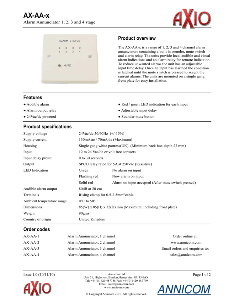
The AX-AA-x is a range of 1, 2, 3 and 4 channel alarm
annunciators containing a built in sounder, mute switch
and alarm relay. The units provide local audible and visual
alarm indications and an alarm relay for remote indication.
To reduce unwanted alarms the unit has an adjustable
input time delay. Once an input has alarmed the condition
is latched until the mute switch is pressed to accept the
current alarms. The units are mounted on a single gang
front plate for easy installation.
Features
● Audible alarm
● Red / green LED indication for each input
● Alarm output relay
● Adjustable input delay
● 24Vac/dc powered
● Sounder mute button
Product specifications
Supply voltage
24Vac/dc 50/60Hz (+/-15%)
Supply current
130mA ac / 70mA dc (Maximum)
Housing
Single gang white pattress(UK). (Minimum back box depth 22 mm)
Input
12 to 24 Vac/dc or volt free contacts
Input delay preset
0 to 30 seconds
Output
SPCO relay rated for 5A at 250Vac (Resistive)
LED Indication
Green
No alarm on input
Flashing red
New alarm on input
Solid red
Alarm on input accepted (After mute switch pressed)
Audible alarm output
80dB at 20 cm
Terminals
Rising clamp for 0.5-2.5mm2 cable
Ambient temperature range
0°C to 50°C
Dimensions
85(W) x 85(H) x 32(D) mm (Maximum, including front plate)
Weight
90gms
Country of origin
United Kingdom
Order codes
AX-AA-1
Alarm Annunciator, 1 channel
Order online at:
AX-AA-2
Alarm Annunciator, 2 channel
www.annicom.com
AX-AA-3
Alarm Annunciator, 3 channel
Email orders and enquiries to:
AX-AA-4
Alarm Annunciator, 4 channel
sales@annicom.com
Issue 1.0 (10/11/10)
Annicom Ltd
Unit 21, Highview, Bordon,Hampshire. GU35 0AX.
Tel: +44(0)1420 487788 Fax: +44(0)1420 487799
Email: sales@annicom.com
www.annicom.com
© Copyright Annicom 2010. All rights reserved.
Page 1 of 2
AX-AA-x
Alarm Annunciator 1, 2, 3 and 4 stage
Installation
The AX-AA-x should be installed by a suitably qualified technician in conjunction with any guidelines for the
equipment it is to be connected to and local regulations. Field wiring should be installed to satisfy the requirements set
out by the manufacturer of the equipment that the module is being connected to.
Mounting The unit is designed to fit to a single gang backbox(UK).
Description and connections
On detection of an alarm input and input delay expiry the sounder is triggered, the channel LED flashes red and the
alarm relay is energised. Pressing the mute button will stop the audible warning and accept the alarm condition. If the
alarm condition has already cleared the channel LED will return to green. If the alarm condition persists when the mute
button is pressed the channel LED stays permanently red until the alarm condition is cleared. The alarm relay will only
de-energise after the mute button has been pressed to silence the sounder and all alarm inputs have been cleared, at
which point all the LEDs will be green. Subsequent alarm conditions will re-trigger the above events.
Inputs The unit accepts 12 to 24 Vac/dc or volt free contacts. The volt free contacts should be connected between 24V
OUT and the channel input.
Input delay In order to reduce spurious triggering the unit will only trigger when the input alarm condition is present
longer then the input delay time. The input delay time is adjustable between 0 and 30 seconds.
LED test Hold mute button down for five seconds to check LEDs
1 Channel alarm annunciator
Note: The diagram shows a 4 channel unit. Only the relevant input terminals are
fitted to 1, 2 and 3 channel units.
Every effort has been taken in the production of this datasheet to ensure accuracy. Annicom Ltd do not accept
responsibility for any damage, expense, injury, loss or consequential loss resulting from any errors or omissions.
Annicom Ltd has a policy of continuous improvement and reserves the right to change this specification without notice.
Issue 1.0 (10/11/10)
Annicom Ltd
Unit 21, Highview, Bordon,Hampshire. GU35 0AX.
Tel: +44(0)1420 487788 Fax: +44(0)1420 487799
Email: sales@annicom.com
www.annicom.com
© Copyright Annicom 2010. All rights reserved.
Page 2 of 2


