Trinetics® Vacuum-Type Capacitor Switches

Trinetics
®
Vacuum-Type Capacitor Switches
Technical Data Sheet
VS Series Technical Information
The VS Series vacuum switch is a single pole device designed to meet or exceed rigorous industry standards. The switch is constructed of a high performance vacuum interrupter specially insulated with a quality mineral oil.
The VS Series vacuum interrupter has several distinct advantages: compact size, short stroke, high reliability, enclosed arc and virtually maintenance-free operation. The design of the interrupter is conceptually simple — two separable contacts within an evacuated envelope. In practice, the design is quite complex, involving carefully selected contact materials integrated with assembly, joining and vacuum processing techniques.
The VS Series vacuum switch can be operated using a time switch, a single or double throw switch, a voltage or currentsensitive device, or by the manual lever. In the automatic mode, the motor output torque is amplified by a permanently lubricated, steel-to-steel gear train enclosed in a die-cast housing. A series of toggle links connects the motor output to the vacuum interrupter to open and close the switch. The neutral lead from the motor and the tank should be properly grounded for safety and to prevent damage from transient voltage surges.
Heavy-duty components ensure quality protection of the internal vacuum interrupter. The steel tank is painted with an
ASA 70 gray polyester powder paint. The finish meets or exceeds the requirements of A.N.S.I. C57.12.31 current revision.
A weather shield protects the high-visibility, yellow manual lever from inclement conditions while providing complete access for manual operation.
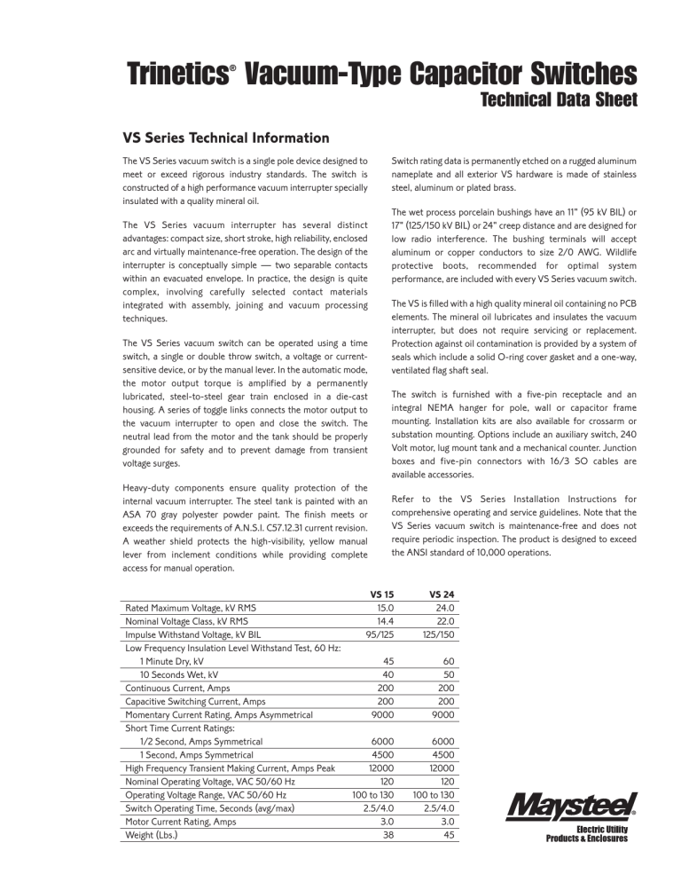
Rated Maximum Voltage, kV RMS
Nominal Voltage Class, kV RMS
Impulse Withstand Voltage, kV BIL
Low Frequency Insulation Level Withstand Test, 60 Hz:
1 Minute Dry, kV
10 Seconds Wet, kV
Continuous Current, Amps
Capacitive Switching Current, Amps
Momentary Current Rating, Amps Asymmetrical
Short Time Current Ratings:
1/2 Second, Amps Symmetrical
1 Second, Amps Symmetrical
High Frequency Transient Making Current, Amps Peak
Nominal Operating Voltage, VAC 50/60 Hz
Operating Voltage Range, VAC 50/60 Hz
Switch Operating Time, Seconds (avg/max)
Motor Current Rating, Amps
Weight (Lbs.)
VS 15
15.0
14.4
95/125
45
40
200
200
9000
6000
4500
12000
120
100 to 130
2.5/4.0
3.0
38
6000
4500
12000
120
100 to 130
2.5/4.0
3.0
45
VS 24
24.0
22.0
125/150
60
50
200
200
9000
Switch rating data is permanently etched on a rugged aluminum nameplate and all exterior VS hardware is made of stainless steel, aluminum or plated brass.
The wet process porcelain bushings have an 11" (95 kV BIL) or
17" (125/150 kV BIL) or 24" creep distance and are designed for low radio interference. The bushing terminals will accept aluminum or copper conductors to size 2/0 AWG. Wildlife protective boots, recommended for optimal system performance, are included with every VS Series vacuum switch.
The VS is filled with a high quality mineral oil containing no PCB elements. The mineral oil lubricates and insulates the vacuum interrupter, but does not require servicing or replacement.
Protection against oil contamination is provided by a system of seals which include a solid O-ring cover gasket and a one-way, ventilated flag shaft seal.
The switch is furnished with a five-pin receptacle and an integral NEMA hanger for pole, wall or capacitor frame mounting. Installation kits are also available for crossarm or substation mounting. Options include an auxiliary switch, 240
Volt motor, lug mount tank and a mechanical counter. Junction boxes and five-pin connectors with 16/3 SO cables are available accessories.
Refer to the VS Series Installation Instructions for comprehensive operating and service guidelines. Note that the
VS Series vacuum switch is maintenance-free and does not require periodic inspection. The product is designed to exceed the ANSI standard of 10,000 operations.
®
Technical
Data Sheet
VS Series Dimensions
Outline dimensions for the VS Series vacuum switch depicting pole, lug, crossarm or substation mounting. Note: The drawing above provides dimensions that are identical for each VS Series vacuum switch and the chart at right indicates dimensions that vary depending on switch type. The columns of the chart reflect dimensions for each switch type based on rated maximum voltage and kV BIL. All drawing and chart dimensions are in inches.
E
F
C
D
G
Dimension
Letter
A
B
VS 15
95
7 3 /
4
15
10 1 /
2
27 1 /
4
7 3 /
4
12 3 /
4
5 1 /
2
VS 15
125
8 1 /
2
15
10 1 /
2
29 1 /
4
7 3 /
4
12 3 /
4
5 1 /
2
VS 24
125
8 1 /
2
15
10 1 /
2
29 1 /
4
7 3 /
4
12 3 /
4
5 1 /
2
VS 24
150
8 1 /
2
15
10 1 /
2
29 1 /
4
7 3 /
4
12 3 /
4
5 1 /
2
VS Series Connections
w w w . m a y s t e e l . c o m
MAYSTEEL Electric Utility Products & Enclosures N90 W14507 Commerce Drive • Menomonee Falls, WI 53052-1240 • 262/251-1632 • 262/251-5895 Fax
SPEC103-7/02


