Stratix GX Built-In Self Test (BIST), Stratix GX Device
advertisement

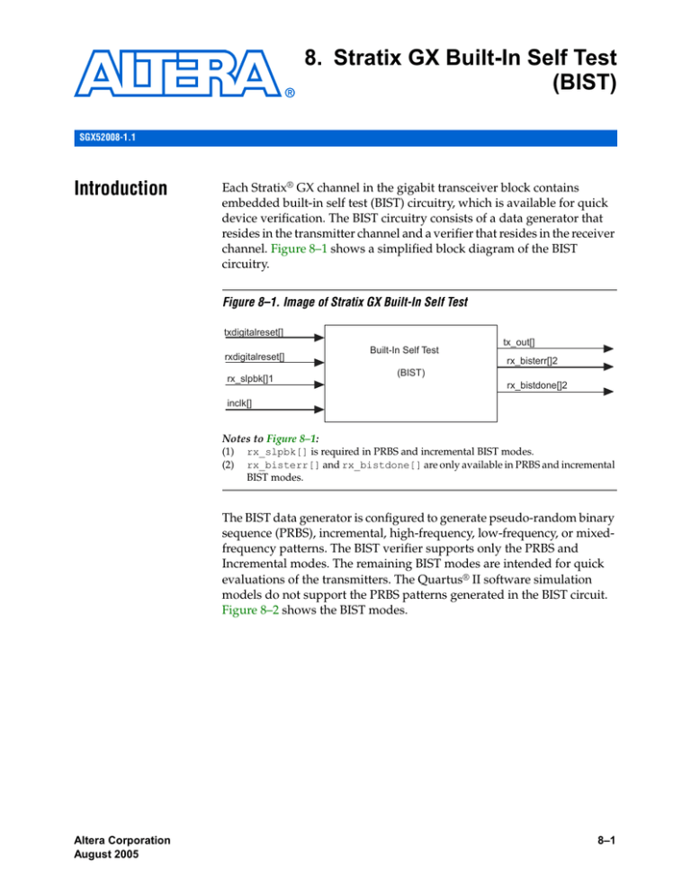
8. Stratix GX Built-In Self Test (BIST) SGX52008-1.1 Introduction Each Stratix® GX channel in the gigabit transceiver block contains embedded built-in self test (BIST) circuitry, which is available for quick device verification. The BIST circuitry consists of a data generator that resides in the transmitter channel and a verifier that resides in the receiver channel. Figure 8–1 shows a simplified block diagram of the BIST circuitry. Figure 8–1. Image of Stratix GX Built-In Self Test txdigitalreset[] rxdigitalreset[] rx_slpbk[]1 Built-In Self Test tx_out[] rx_bisterr[]2 (BIST) rx_bistdone[]2 inclk[] Notes to Figure 8–1: (1) (2) rx_slpbk[] is required in PRBS and incremental BIST modes. rx_bisterr[] and rx_bistdone[] are only available in PRBS and incremental BIST modes. The BIST data generator is configured to generate pseudo-random binary sequence (PRBS), incremental, high-frequency, low-frequency, or mixedfrequency patterns. The BIST verifier supports only the PRBS and Incremental modes. The remaining BIST modes are intended for quick evaluations of the transmitters. The Quartus® II software simulation models do not support the PRBS patterns generated in the BIST circuit. Figure 8–2 shows the BIST modes. Altera Corporation August 2005 8–1 Pattern Generator Figure 8–2. Block Diagram of BIST Modes BIST MODES PATTERN GENERATOR PATTERN VERIFIER (Transmitter) INCREMENTAL PRBS 10^ 8 -1 Pattern Generator HIGH PRBS Frequency (Receiver) LOW MIX Frequency PRBS Frequency PRBS 10^ 10-1 PRBS 10^ 8-1 INCREMENTAL PRBS 10^ 10-1 The BIST data generator supports the following pattern generators: ■ ■ ■ ■ ■ PRBS mode generator Incremental mode generator High-frequency mode generator Low-frequency mode generator Mix-frequency mode generator PRBS Mode Generator Pseudo-Random Bit Sequences (PRBS) are commonly used to verify the integrity and robustness of the data transmission paths. The PRBS generator is used in 8-, 16-, 10-, or 20-bit modes. In 8- or 16-bit data width modes, the PRBS generator generates 28-1 unique patterns. In 10- or 20-bit data modes, the PRBS generator yields 210-1 unique patterns. Table 8–1 lists the modes and their associated polynomials. Table 8–1. BIST Generator PRBS Modes Data Width PRBS Mode Polynomials 8-bit 28-1 X8 10-bit 210-1 X10 + X7 + 1 16-bit 28-1 X8 + X 7 + X5 + X 3 + 1 20-bit 210-1 X10 + X7 + 1 8–2 Stratix GX Device Handbook, Volume 2 + X 7 + X5 + X 3 + 1 Altera Corporation August 2005 Stratix GX Built-In Self Test (BIST) PRBS mode is enabled when the PRBS option is enabled in the Quartus II software. The 8b-10b encoder/decoder is bypassed automatically in this mode. You can use PRBS generation to test the functionality of both the transmitter and receiver, to test if the BIST verifier is enabled, or to measure the quality of the transmission medium. The advantage of using a PRBS data stream is that the randomness yields an environment that stresses the transmission medium. In the data stream both random jitter and deterministic jitter are observed either by a time interval analyzer (TIA), a bit error rate tester, or an oscilloscope. Incremental Mode Generator In the incremental mode, the data generator sweeps through all the valid 8b/10b data and control characters. You can also enable the incremental BIST verifier to perform a quick verification of the 8B/10B encoder/decoder paths. Refer to “Pattern Verifier” on page 8–5 for more information. Incremental mode is enabled when option 1 is selected under the what self test mode do you want to use? option in the Quartus II software. In this mode, the BIST generator sends out the data pattern in the following sequence: K28.5 (comma), K27.7 (Start of Frame, SOF), Data (00-FF incremental), K28.0, K28.1, K28.2, K28.3, K28.4, K28.6, K28.7, K23.7, K30.7, K29.7 (End of Frame, EOF) and repeat. The 8b/10b encoder must be enabled for proper operation. Because the 8/b10b encoder is enabled, the data stream is DC balanced. 8b/10b encoding guarantees a run length less than 5 UI, which yields a less stressful pattern than the PRBS data. However, because the PRBS generator bypasses the 8b/10b paths, you can use the incremental BIST to test this path. High-Frequency Mode Generator In high-frequency mode, the BIST generator transmits a D21.5 ±(8'b10110101) character into the 8b/10b encoder to generate a 10'b1010101010 high-frequency character. This toggling data is the highest frequency that the data stream can transmit. This pattern is DC balanced; the number of ones is equal to number of zeros. This fact is important when trying to perform a first-order random jitter measurement. You can measure this jitter using an oscilloscope with a histogram defined at the zero crossing point. This method is crude, but still yields a first-order estimated value, because the majority of the Altera Corporation August 2005 8–3 Stratix GX Device Handbook, Volume 2 Pattern Generator deterministic data dependant components are masked out. However, for more accurate measurements, use a TIA or some type of jitter separation software to break down the random and deterministic components. High-frequency mode is also useful when trying to characterize the high-frequency losses in the time domain. The delta amplitude difference between the high-frequency pattern and the low-frequency pattern can give you a first-order approximation of the high-frequency losses due to the skin effect and dielectric losses. This method is useful only for a first-order approximation; use extractions of RLGC values with 2D and 3D field solvers to determine more accurate loss coefficients. High-frequency mode is enabled when option 2 is selected in the Quartus II software under what self test mode do you want to use? Enable the 8b/10b encoder to generate the high-frequency pattern. If it is disabled, an 8'b10110101 character is sent instead of the 10'b1010101010 character. Low-Frequency Mode Generator In low-frequency mode, the BIST generator transmits a K28.7 -/+ character (8'b11111100) into the 8b/10b encoder to generate a 10'b0011111000 or 10'b1100000111 low-frequency character. The low-frequency data transition toggles at one-tenth the data rate of the high-frequency pattern. Like the high-frequency pattern, the low-frequency pattern is DC balanced with the number of ones equal to the number of zeros. This fact is important when trying to perform a first order random jitter measurement. You can measure this jitter using an oscilloscope with a histogram defined at the zero crossing point. This method is crude, but still yields a first-order estimated value, because the majority of the deterministic data-dependant components are masked out. However, for more accurate measurements, use a TIA or some type of jitter separation software to break down the random and deterministic components. Because the data transitions in a slower frequency, the signal is less prone to high-frequency losses. As a result, the signal is able to rise to a higher amplitude than the high-frequency components. Therefore, the delta between the two measurements yields a first order approximation of the high-frequency losses in the time domain. Once again, this approach is useful only for a first-order approximation. Use extractions of RLGC values with 2D and 3D field solvers to determine more accurate loss coefficients. 8–4 Stratix GX Device Handbook, Volume 2 Altera Corporation August 2005 Stratix GX Built-In Self Test (BIST) Low-frequency mode is enabled when you select the SELF_ option 3 in the Quartus II software under what self test mode do you want to use? You must enable the 8b/10b encoder to generate the high-frequency pattern. If it is disabled, an 8'b11111100 character is sent instead of the 10'b0011111000 or 10'b1100000111 characters. Mix-Frequency Mode Generator In mix-frequency mode, the BIST generator transmits a K28.5 -/+ character (8'b10111100) character into the 8b/10b encoder to generate a 10'b0011111010 or 10'b1100000101 mixed-frequency character. The mixed frequency pattern contains both high-frequency and low-frequency components. This approach is useful for first-order approximation of the frequency response of the transmission medium. If captured with an oscilloscope, these frequency responses are approximated in time domain. Mix-frequency mode is enabled when you select option 4 in the Quartus II software under what self test mode do you want to use? As in the high-frequency and low-frequency modes, you must enable the 8b/10b encoder in order to generate the mixed-frequency pattern. Pattern Verifier The BIST verifier supports the PRBS and incremental modes. PRBS Mode Verifier The PRBS verifier provides a quick check through the non-8b/10b path of the transceiver block. You must select the internal or external loopback mode to loop the generated data back into the verifier in the receiver. Select either a serial or parallel loopback to provide this path. A parallel loopback tests the digital portion of the transceiver while a serial loopback also tests the analog clock recovery unit (CRU) and the serializer and deserializer. The PRBS verifier is active when the receiver channel is synchronized. The alignment pattern must be set to 16'b1000000011111111 for the 8- and 16-bit modes and to 10'b111111111 for the 10- and 20-bit modes. The data is synchronized automatically with a built in state machine, so the rx_enacdet signal is not required. The verifier stops checking the patterns after receiving all the PRBS patterns (255 patterns for 8-bit mode and 1023 patterns for 10-bit mode). The rx_bistdone signal goes high, indicating that the verifier has completed. If the verifier detects an error before it is finished, rx_bisterr goes high and the value will be latched until it is reset. The rxdigitalreset signal must be used to re-start the PRBS verification. Altera Corporation August 2005 8–5 Stratix GX Device Handbook, Volume 2 Pattern Verifier Be sure you do not use the rx_apllreset signal because the re-training process of the CRU might cause false errors. A reference design is included in “Design Examples” on page 8–7. Incremental Mode Verifier In the incremental mode, the BIST generator transmits the data pattern in the following sequence: K28.5 (comma), K27.7 (SOF), Data (00-FF incremental), K28.0, K28.1, K28.2, K28.3, K28.4, K28.6, K28.7, K23.7, K30.7, K29.7 (EOF), and repeat. The sync pattern on the receiver word aligner must be set to a K28.5 pattern (10'b0011111010) for proper synchronization between the generator and verifier. As in the PRBS verification mode, the synchronization is handled by a built-in state machine, so control of the rx_enacdet signal is not required. The BIST verifier waits for the word aligner to synchronize. After synchronization, the BIST verifier checks for the following sequence: K27.7 (SOF), Data (00-FF incremental), K28.0, K28.1, K28.2, K28.3, K28.4, K28.6, K28.7, K23.7, K30.7, and K29.7 (EOF). If it does not see a K27.7 (SOF) within 31 patterns, the rx_errdetect and rx_bistdone signals go high, and the verifier stops. The verifier checks for this sequence twice before setting the rx_bistdone signal high. If any errors are detected before the verifier finishes, the rx_errdetect and rx_bistdone signals go high. Use the rxdigitalreset signal to restart the incremental verification. Do not use the rxanalogreset signal because the retraining process of the CRU might cause false errors. A reference design is included in “Design Examples” on page 8–7. Table 8–2 shows which loopback modes are supported for each verification mode. Table 8–2. Verification Modes Verification Mode Comma Loopback Modes 28-1 16'b1000000011111111 (A1A2 mode) Serial or parallel 210-1 10'b111111111 (10-bit mode) Serial or parallel Incremental 10'b0011111010 (10-bit mode) Serial or parallel or post 8B/10B parallel 8–6 Stratix GX Device Handbook, Volume 2 Altera Corporation August 2005 Stratix GX Built-In Self Test (BIST) Design Examples The purpose of these design examples are to show how to instantiate and operate the various BIST modes in Stratix GX devices. The following reference designs cover: ■ ■ ■ ■ ■ PRBS BIST generator and verification design Incremental BIST generator and verification design High-frequency transmitter generation design Low-frequency transmitter generation design Mixed-frequency transmitter generation design Design 1: PRBS BIST Generator & Verification Design This design shows how to use the BIST in PRBS 210-1 mode. You can also apply this design principle to the 28-1 by changing the data-width mode, comma, and word-alignment mode as listed in Table 8–2 on page 8–6. A useful circuit to include in the PRBS verifier is a self-timed reset controller. This controller prevents bounce conditions that might occur when an external switch is used. This design consists of a reset module (reset.v) that periodically toggles the rxdigitalreset signal of the altgxb instantiation (PRBS_BIST.v). Figure 8–3 shows a block diagram of this design. Figure 8–3. Block Diagram of the PRBS BIST Design rx_in PRBS_BIST inclk[0] rx_in[0] inclk reset_mod clk reset reset_mod_inst tx_out[0] coreclk_out[0] rx_slpbk[0] rx_clkout[0] rxdigitalreset[0] rx_bistdone[0] rx_bisterr[0] tx_out coreclk_out rx_clkout rx_bistdone rx_bisterr PRBS_BIST_inst reset Top-Level Design (PRBS.v) module PRBS( inclk, rx_in, coreclk_out, tx_out, rx_bisterr, rx_bistdone, rx_clkout, reset ); Altera Corporation August 2005 8–7 Stratix GX Device Handbook, Volume 2 Design Examples input input output output output output output output inclk; rx_in; coreclk_out; tx_out; rx_bisterr; rx_bistdone; rx_clkout; reset; wire wire assign assign reset_wire; VCC; reset = reset_wire; VCC = 1; //Altgxb Instantiation//////////////////////////// PRBS_BIST PRBS_BIST_inst( .inclk(inclk), .rx_in(rx_in), .rx_slpbk(VCC), .rxdigitalreset(reset_wire), .coreclk_out(coreclk_out), .rx_bistdone(rx_bistdone), .rx_bisterr(rx_bisterr), .rx_clkout(rx_clkout), .tx_out(tx_out)); //Reset Module Instantiation////////////////// reset_mod .clk(inclk), .reset(reset_wire)); endmodule reset_mod_inst( Reset Module Design (reset_mod.v) module reset_mod(clk, reset); input clk; output reset; reg [19:0] counter; reg reset; always @ (posedge clk) counter = counter +1; always @ (counter) begin if ((counter >= 20'b11111111111111100000) && (counter <= 20'b11111111111111111111)) reset = 1'b1; else reset = 1'b0; end 8–8 Stratix GX Device Handbook, Volume 2 Altera Corporation August 2005 Stratix GX Built-In Self Test (BIST) endmodule altgxb Instantiation (PRBS_BIST.v) module PRBS_BIST ( inclk, rx_in, rx_slpbk, rxdigitalreset, tx_out, coreclk_out, rx_clkout, rx_bistdone, rx_bisterr); input[ input[ input input output output output output output wire wire wire wire wire wire wire wire wire wire 0:0] inclk; 0:0] rx_in; [0:0] rx_slpbk; [0:0] rxdigitalreset; [0:0] tx_out; [0:0] coreclk_out; [0:0] rx_clkout; [0:0] rx_bistdone; [0:0] rx_bisterr; [0:0] [0:0] [0:0] [0:0] [0:0] [0:0] [0:0] [0:0] [0:0] [0:0] sub_wire0; sub_wire1; sub_wire2; sub_wire3; sub_wire4; tx_out = sub_wire0[0:0]; coreclk_out = sub_wire1[0:0]; rx_clkout = sub_wire2[0:0]; rx_bistdone = sub_wire3[0:0]; rx_bisterr = sub_wire4[0:0]; altgxbaltgxb_component ( .inclk (inclk), .rx_in (rx_in), .rx_slpbk (rx_slpbk), .rxdigitalreset (rxdigitalreset), Altera Corporation August 2005 8–9 Stratix GX Device Handbook, Volume 2 Design Examples .tx_out (sub_wire0), .coreclk_out (sub_wire1), .rx_clkout (sub_wire2), .rx_bistdone (sub_wire3), .rx_bisterr (sub_wire4)); defparam altgxb_component.force_disparity_mode = "OFF", altgxb_component.channel_width = 20, altgxb_component.pll_inclock_period = 6400, altgxb_component.use_symbol_align = "ON", altgxb_component.rx_ppm_setting = 1000, altgxb_component.pll_bandwidth_type = "LOW", altgxb_component.dwidth_factor = 2, altgxb_component.number_of_channels = 1, altgxb_component.vod_ctrl_setting = 1000, altgxb_component.align_pattern_length = 10, altgxb_component.use_self_test_mode = "ON", altgxb_component.lpm_type = "altgxb", altgxb_component.use_fifo_mode = "ON", altgxb_component.use_vod_ctrl_signal = "OFF", altgxb_component.equalizer_ctrl_setting = 0, altgxb_component.use_auto_bit_slip = "ON", altgxb_component.use_rate_match_fifo = "OFF", altgxb_component.signal_threshold_select = 80, altgxb_component.self_test_mode = 0, altgxb_component.use_double_data_mode = "ON", altgxb_component.use_preemphasis_ctrl_signal = "OFF", altgxb_component.protocol = "CUSTOM", altgxb_component.clk_out_mode_reference = "ON", altgxb_component.rx_bandwidth_type = "LOW", altgxb_component.disparity_mode = "ON", altgxb_component.preemphasis_ctrl_setting = 0, altgxb_component.loopback_mode = "SLB", altgxb_component.use_channel_align = "OFF", altgxb_component.intended_device_family = "Stratix GX", altgxb_component.use_equalizer_ctrl_signal = "OFF", altgxb_component.rx_enable_dc_coupling = "OFF", altgxb_component.run_length_enable = "OFF", altgxb_component.pll_use_dc_coupling = "OFF", altgxb_component.operation_mode = "DUPLEX", altgxb_component.use_8b_10b_mode = "OFF", altgxb_component.use_rx_clkout = "ON", altgxb_component.data_rate_remainder = 0, 8–10 Stratix GX Device Handbook, Volume 2 Altera Corporation August 2005 Stratix GX Built-In Self Test (BIST) altgxb_component.data_rate = 3125, altgxb_component.align_pattern = "P1111111111", altgxb_component.use_rx_cruclk = "OFF", altgxb_component.number_of_quads = 1; endmodule Results A quick method for verifying whether the BIST verification passes or fails is to use the SignalTap® II logic analyzer in the Quartus® II software. Refer to Application Note 280: Design Verification Using the SignalTap II Logic Analyzer for more information on using the SignalTap II logic analyzer. The SignalTap II logic analyzer trigger is set to the falling edge of the reset output signal. Figure 8–4 is a screen shot of the SignalTap II logic analyzer results for this PRBS BIST test. Figure 8–4. SignalTap II Logic Analyzer Results for PRBS BIST Test Design (2) (3) (1) Resets the Verifier rx_bistdone signifies that the verification cycle is complete rx_bisterr remains low, signifying no bit errors Design 2: Incremental BIST Generator & Verification Design This design is similar to the PRBS BIST generator and verification design, except the altgxb megafunction is configured to the incremental BIST mode. Refer to the design for information on the ports and parameters required for altgxb in this mode. As in the PRBS design, a useful circuit to include in the PRBS verifier is a self-timed reset controller. This controller prevents bounce conditions that might occur when an external switch is used. This design consists of a reset module (reset.v) that periodically toggles the rxdigitalreset signal of the altgxb instantiation (Incremental_BIST.v). Figure 8–5 shows a block diagram of this design. Altera Corporation August 2005 8–11 Stratix GX Device Handbook, Volume 2 Design Examples Figure 8–5. Block Diagram of the Incremental BIST Design rx_in Incr_BIST inclk[0] rx_in[0] inclk reset_mod clk reset reset_mod_inst rx_slpbk[0] tx_out[0] coreclk_out[0] rx_clkout[0] rxdigitalreset[0] rx_bistdone[0] rx_bisterr[0] tx_out coreclk_out rx_clkout rx_bistdone rx_bisterr Incr_BIST_inst reset Top-Level Design (Incremental) module incremental( inclk, rx_in, coreclk_out, tx_out, rx_bisterr, rx_bistdone, rx_clkout, reset ); input inclk; input rx_in; outputcoreclk_out; output tx_out; outputrx_bisterr; output rx_bistdone; output rx_clkout; output reset; wire wire reset_wire; VCC; assign reset = reset_wire; assign VCC = 1; Incr_BIST .inclk(inclk), .rx_in(rx_in), .rx_slpbk(VCC), .rxdigitalreset(reset_wire), 8–12 Stratix GX Device Handbook, Volume 2 Incr_BIST_inst( Altera Corporation August 2005 Stratix GX Built-In Self Test (BIST) .coreclk_out(coreclk_out), .rx_bistdone(rx_bistdone), .rx_bisterr(rx_bisterr), .rx_clkout(rx_clkout), .tx_out(tx_out)); reset_mod reset_mod_inst( .clk(inclk), .reset(reset_wire)); endmodule Reset Module Design (reset_mod.v) module reset_mod(clk, reset); input clk; output reset; reg [19:0] counter; reg reset; always @ (posedge clk) counter = counter +1; always @ (counter) begin if ((counter >= 20'b11111111111111100000) && (counter <= 20'b11111111111111111111)) reset = 1'b1; else reset = 1'b0; end endmodule altgxb Instantiation (Incr_BIST.v) module Incr_BIST ( inclk, rx_in, rx_slpbk, rxdigitalreset, tx_out, coreclk_out, rx_clkout, rx_bistdone, rx_bisterr); Altera Corporation August 2005 8–13 Stratix GX Device Handbook, Volume 2 Design Examples input input input input output output output output output [0:0] [0:0] [0:0] [0:0] [0:0] [0:0] [0:0] [0:0] [0:0] inclk; rx_in; rx_slpbk; rxdigitalreset; tx_out; coreclk_out; rx_clkout; rx_bistdone; rx_bisterr; wire [0:0] sub_wire0; wire [0:0] sub_wire1; wire [0:0] sub_wire2; wire wire wire wire wire wire wire [0:0] sub_wire3; [0:0] sub_wire4; [0:0] tx_out = sub_wire0[0:0]; [0:0] coreclk_out = sub_wire1[0:0]; [0:0] rx_clkout = sub_wire2[0:0]; [0:0] rx_bistdone = sub_wire3[0:0]; [0:0] rx_bisterr = sub_wire4[0:0]; altgxb altgxb_component ( .inclk (inclk), rx_in (rx_in), .rx_slpbk (rx_slpbk), .rxdigitalreset (rxdigitalreset), .tx_out (sub_wire0), .coreclk_out (sub_wire1), .rx_clkout (sub_wire2), .rx_bistdone (sub_wire3), .rx_bisterr (sub_wire4)); defparam altgxb_component.force_disparity_mode = "OFF", altgxb_component.channel_width = 16, altgxb_component.pll_inclock_period = 6250, altgxb_component.use_symbol_align = "ON", altgxb_component.rx_ppm_setting = 1000, altgxb_component.pll_bandwidth_type = "LOW", altgxb_component.dwidth_factor = 2, altgxb_component.number_of_channels = 1, altgxb_component.vod_ctrl_setting = 1000, altgxb_component.align_pattern_length = 10, altgxb_component.use_self_test_mode = "ON", 8–14 Stratix GX Device Handbook, Volume 2 Altera Corporation August 2005 Stratix GX Built-In Self Test (BIST) altgxb_component.lpm_type = "altgxb", altgxb_component.use_fifo_mode = "ON", altgxb_component.use_vod_ctrl_signal = "OFF", altgxb_component.equalizer_ctrl_setting = 0, altgxb_component.use_auto_bit_slip = "ON", altgxb_component.use_rate_match_fifo = "OFF", altgxb_component.signal_threshold_select = 80, altgxb_component.self_test_mode = 1, altgxb_component.use_double_data_mode = "ON", altgxb_component.use_preemphasis_ctrl_signal = "OFF", altgxb_component.protocol = "CUSTOM", altgxb_component.clk_out_mode_reference = "ON", altgxb_component.rx_bandwidth_type = "LOW", altgxb_component.disparity_mode = "ON", altgxb_component.preemphasis_ctrl_setting = 0, altgxb_component.loopback_mode = "SLB", altgxb_component.use_channel_align = "OFF", altgxb_component.intended_device_family = "Stratix GX", altgxb_component.use_equalizer_ctrl_signal = "OFF", altgxb_component.rx_enable_dc_coupling = "OFF", altgxb_component.run_length_enable = "OFF", altgxb_component.pll_use_dc_coupling = "OFF", altgxb_component.operation_mode = "DUPLEX", altgxb_component.use_8b_10b_mode = "ON", altgxb_component.use_rx_clkout = "ON", altgxb_component.data_rate_remainder = 0, altgxb_component.data_rate = 2560, altgxb_component.align_pattern = "P0011111010", altgxb_component.use_rx_cruclk = "OFF", altgxb_component.number_of_quads = 1; endmodule Results A quick method for verifying whether the BIST verification passes or fails is to use the SignalTap II embedded logic analyzer in the Quartus II software. Refer to Application Note 280: Design Verification Using the SignalTap II Logic Analyzer for more information. The SignalTap II trigger is set to the falling edge of the reset output signal. Figure 8–6 is a screen shot of the SignalTap II results for the incremental BIST results. Altera Corporation August 2005 8–15 Stratix GX Device Handbook, Volume 2 Design Examples Figure 8–6. SignalTap II Results for PRBS BIST Test Design (Resets the Verifier) (2) (3) (1) rx_bistdone signifies that the verification cycle is complete resets the verifier rx_bisterr remains low, signifying no bit errors Design 3: High-Frequency Transmitter Generator Design This design shows how to instantiate the altgxb megafunction in the high-frequency BIST mode. Because this design consists only of a single transmitter design, only the altgxb instantiation is shown. The top level simply consists of calling the megafunction instance. altgxb Instantiation (High_Freq_BIST.v) module high_freq_BIST ( inclk, tx_out, coreclk_out); input [ 0:0] inclk; output [0:0] tx_out; output [0:0] coreclk_out; wire wire wire wire [0:0] [0:0] [0:0] [0:0] altgxb sub_wire0; sub_wire1; tx_out = sub_wire0[0:0]; coreclk_out = sub_wire1[0:0]; altgxb_component ( .inclk (inclk), .tx_out (sub_wire0), .coreclk_out (sub_wire1)); defparam altgxb_component.force_disparity_mode = "OFF", altgxb_component.channel_width = 16, 8–16 Stratix GX Device Handbook, Volume 2 Altera Corporation August 2005 Stratix GX Built-In Self Test (BIST) , , = 1000, altgxb_component.pll_inclock_period = 6250, altgxb_component.pll_bandwidth_type = "LOW" altgxb_component.dwidth_factor = 2, altgxb_component.number_of_channels = 1 altgxb_component.vod_ctrl_setting altgxb_component.use_self_test_mode = "ON", altgxb_component.lpm_type = "altgxb", altgxb_component.use_fifo_mode = "ON", altgxb_component.use_vod_ctrl_signal = "OFF", altgxb_component.self_test_mode = 2, altgxb_component.use_double_data_mode = "ON", altgxb_component.use_preemphasis_ctrl_signal = "OFF", altgxb_component.protocol = "CUSTOM", altgxb_component.clk_out_mode_reference = "ON", altgxb_component.preemphasis_ctrl_setting = 0, altgxb_component.use_channel_align = "OFF", altgxb_component.intended_device_family = "Stratix GX", altgxb_component.pll_use_dc_coupling = "OFF", altgxb_component.operation_mode = "TX", altgxb_component.use_8b_10b_mode = "ON", altgxb_component.use_rx_clkout = "OFF", altgxb_component.data_rate_remainder = 0, altgxb_component.data_rate = 2560, altgxb_component.use_rx_cruclk = "OFF", altgxb_component.number_of_quads = 1; endmodule Results Figure 8–7 shows a screen shot of the high-frequency BIST mode. The signal was captured using a sampling oscilloscope. Altera Corporation August 2005 8–17 Stratix GX Device Handbook, Volume 2 Design Examples Figure 8–7. High-Frequency BIST Measured on tx_out[] Design 4: Low-Frequency Transmitter Generator Design This design shows how to instantiate the altgxb megafunction in the low-frequency BIST mode. Because this design consists only of a single transmitter design, only the altgxb instantiation is shown. The top level simply consists of calling the megafunction instance. altgxb Instantiation (low_freq_BIST.v) module low_freq_BIST ( inclk, tx_out, coreclk_out); input [0:0] output output [0:0] wire wire wire wire 8–18 Stratix GX Device Handbook, Volume 2 [0:0] [0:0] [0:0] [0:0] inclk; [0:0] tx_out; coreclk_out; sub_wire0; sub_wire1; tx_out = sub_wire0[0:0]; coreclk_out = sub_wire1[0:0]; Altera Corporation August 2005 Stratix GX Built-In Self Test (BIST) altgxb altgxb_component ( inclk (inclk), .tx_out (sub_wire0), .coreclk_out (sub_wire1)); defparam altgxb_component.force_disparity_mode = "OFF", altgxb_component.channel_width = 16, altgxb_component.pll_inclock_period = 6250, altgxb_component.pll_bandwidth_type = "LOW", altgxb_component.dwidth_factor = 2, altgxb_component.number_of_channels = 1, altgxb_component.vod_ctrl_setting = 1000, altgxb_component.use_self_test_mode = "ON", altgxb_component.lpm_type = "altgxb", altgxb_component.use_fifo_mode = "ON", altgxb_component.use_vod_ctrl_signal = "OFF", altgxb_component.self_test_mode = 3, altgxb_component.use_double_data_mode = "ON", altgxb_component.use_preemphasis_ctrl_signal = "OFF", altgxb_component.protocol = "CUSTOM", altgxb_component.clk_out_mode_reference = "ON", altgxb_component.preemphasis_ctrl_setting = 0, altgxb_component.use_channel_align = "OFF", altgxb_component.intended_device_family = "Stratix GX", altgxb_component.pll_use_dc_coupling = "OFF", altgxb_component.operation_mode = "TX", altgxb_component.use_8b_10b_mode = "ON", altgxb_component.use_rx_clkout = "OFF", altgxb_component.data_rate_remainder = 0, altgxb_component.data_rate = 2560, altgxb_component.use_rx_cruclk = "OFF", altgxb_component.number_of_quads = 1; endmodule Results The low-frequency BIST mode is shown in Figure 8–8. The signal was captured using a sampling oscilloscope. Altera Corporation August 2005 8–19 Stratix GX Device Handbook, Volume 2 Design Examples Figure 8–8. Low-Frequency BIST Measured on tx_out[] Design 5: Mix-Frequency Transmitter Generator Design The mix-frequency transmitter generator design shows how to instantiate the altgxb megafunction in the mix-frequency BIST mode. Because this design consists only of a single transmitter design, only the altgxb instantiation is shown. The top level simply consists of calling the megafunction instance. altgxb Instantiation (mix_freq_BIST.v) module mix_freq_BIST ( inclk, tx_out, coreclk_out); input output[0:0] output[0:0] wire wire wire wire 8–20 Stratix GX Device Handbook, Volume 2 [0:0] [0:0] [0:0] [0:0] [0:0] inclk; tx_out; coreclk_out; sub_wire0; sub_wire1; tx_out = sub_wire0[0:0]; coreclk_out = sub_wire1[0:0]; Altera Corporation August 2005 Stratix GX Built-In Self Test (BIST) altgxb altgxb_component ( inclk (inclk), .tx_out (sub_wire0), .coreclk_out (sub_wire1)); defparam altgxb_component.force_disparity_mode = "OFF", altgxb_component.channel_width = 16, altgxb_component.pll_inclock_period = 6250, altgxb_component.pll_bandwidth_type = "LOW", altgxb_component.dwidth_factor = 2, altgxb_component.number_of_channels = 1, altgxb_component.vod_ctrl_setting = 1000, altgxb_component.use_self_test_mode = "ON", altgxb_component.lpm_type = "altgxb", altgxb_component.use_fifo_mode = "ON", altgxb_component.use_vod_ctrl_signal = "OFF", altgxb_component.self_test_mode = 4, altgxb_component.use_double_data_mode = "ON", altgxb_component.use_preemphasis_ctrl_signal = "OFF", altgxb_component.protocol = "CUSTOM", altgxb_component.clk_out_mode_reference = "ON", altgxb_component.preemphasis_ctrl_setting = 0, altgxb_component.use_channel_align = "OFF", altgxb_component.intended_device_family = "Stratix GX", altgxb_component.pll_use_dc_coupling = "OFF", altgxb_component.operation_mode = "TX", altgxb_component.use_8b_10b_mode = "ON", altgxb_component.use_rx_clkout = "OFF", altgxb_component.data_rate_remainder = 0, altgxb_component.data_rate = 2560, altgxb_component.use_rx_cruclk = "OFF", altgxb_component.number_of_quads = 1; endmodule Results Figure 8–9 shows a screen shot of the mix-frequency BIST mode. The signal was captured using a sampling oscilloscope. Altera Corporation August 2005 8–21 Stratix GX Device Handbook, Volume 2 Design Examples Figure 8–9. Mix-Frequency BIST Measured on tx_out[] 8–22 Stratix GX Device Handbook, Volume 2 Altera Corporation August 2005


