BiCMOS Integration of High
advertisement

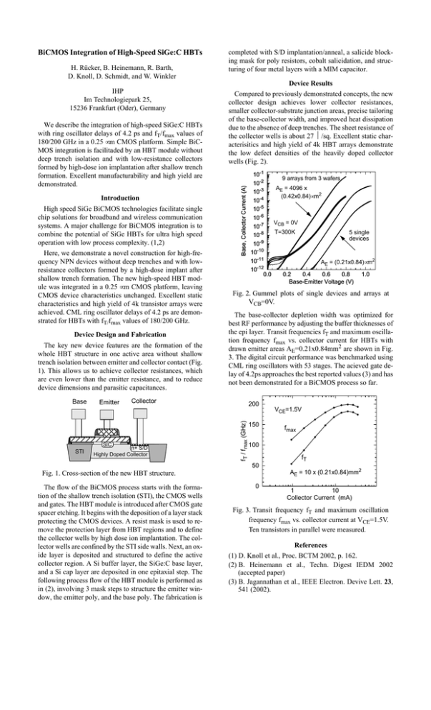
H. Rücker, B. Heinemann, R. Barth, D. Knoll, D. Schmidt, and W. Winkler IHP Im Technologiepark 25, 15236 Frankfurt (Oder), Germany We describe the integration of high-speed SiGe:C HBTs with ring oscillator delays of 4.2 ps and fT/fmax values of 180/200 GHz in a 0.25 µm CMOS platform. Simple BiCMOS integration is facilitaded by an HBT module without deep trench isolation and with low-resistance collectors formed by high-dose ion implantation after shallow trench formation. Excellent manufacturability and high yield are demonstrated. Introduction High speed SiGe BiCMOS technologies facilitate single chip solutions for broadband and wireless communication systems. A major challenge for BiCMOS integration is to combine the potential of SiGe HBTs for ultra high speed operation with low process complexity. (1,2) Here, we demonstrate a novel construction for high-frequency NPN devices without deep trenches and with lowresistance collectors formed by a high-dose implant after shallow trench formation. The new high-speed HBT module was integrated in a 0.25 µm CMOS platform, leaving CMOS device characteristics unchanged. Excellent static characteristics and high yield of 4k transistor arrays were achieved. CML ring oscillator delays of 4.2 ps are demonstrated for HBTs with fT/fmax values of 180/200 GHz. Device Design and Fabrication The key new device features are the formation of the whole HBT structure in one active area without shallow trench isolation between emitter and collector contact (Fig. 1). This allows us to achieve collector resistances, which are even lower than the emitter resistance, and to reduce device dimensions and parasitic capacitances. STI Emitter Device Results Compared to previously demonstrated concepts, the new collector design achieves lower collector resistances, smaller collector-substrate junction areas, precise tailoring of the base-collector width, and improved heat dissipation due to the absence of deep trenches. The sheet resistance of the collector wells is about 27 Ω/sq. Excellent static characterisitics and high yield of 4k HBT arrays demonstrate the low defect densities of the heavily doped collector wells (Fig. 2). The base-collector depletion width was optimized for best RF performance by adjusting the buffer thicknesses of the epi layer. Transit frequencies fT and maximum oscillation frequency fmax vs. collector current for HBTs with drawn emitter areas AE=0.21x0.84mm2 are shown in Fig. 3. The digital circuit performance was benchmarked using CML ring oscillators with 53 stages. The acieved gate delay of 4.2ps approaches the best reported values (3) and has not been demonstrated for a BiCMOS process so far. Collector SIC n+ S/D Highly Doped Collector 10-1 9 arrays from 3 wafers 10-2 A E = 4096 x 10-3 (0.42x0.84)µm2 10-4 10-5 10-6 VCB = 0V 10-7 T=300K 5 single 10-8 devices -9 10 10-10 10-11 AE = (0.21x0.84)µm2 -12 10 0.0 0.2 0.4 0.6 0.8 1.0 Base-Emitter Voltage (V) Fig. 2. Gummel plots of single devices and arrays at VCB=0V. 200 fT / fmax (GHz) Base completed with S/D implantation/anneal, a salicide blocking mask for poly resistors, cobalt salicidation, and structuring of four metal layers with a MIM capacitor. Base, Collector Current (A) BiCMOS Integration of High-Speed SiGe:C HBTs 150 fmax 100 fT 50 Fig. 1. Cross-section of the new HBT structure. The flow of the BiCMOS process starts with the formation of the shallow trench isolation (STI), the CMOS wells and gates. The HBT module is introduced after CMOS gate spacer etching. It begins with the deposition of a layer stack protecting the CMOS devices. A resist mask is used to remove the protection layer from HBT regions and to define the collector wells by high dose ion implantation. The collector wells are confined by the STI side walls. Next, an oxide layer is deposited and structured to define the active collector region. A Si buffer layer, the SiGe:C base layer, and a Si cap layer are deposited in one epitaxial step. The following process flow of the HBT module is performed as in (2), involving 3 mask steps to structure the emitter window, the emitter poly, and the base poly. The fabrication is VCE=1.5V 0 AE = 10 x (0.21x0.84)mm2 1 10 Collector Current (mA) Fig. 3. Transit frequency fT and maximum oscillation frequency fmax vs. collector current at VCE=1.5V. Ten transistors in parallel were measured. References (1) D. Knoll et al., Proc. BCTM 2002, p. 162. (2) B. Heinemann et al., Techn. Digest IEDM 2002 (accepted paper) (3) B. Jagannathan et al., IEEE Electron. Devive Lett. 23, 541 (2002).


